Kawasaki 690551-1HR User Manual
Page 5
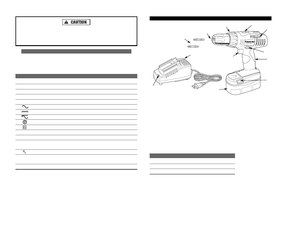
FUNCTIONAL DESCRIPTION
CONTROLS AND COMPONENTS:
1. Battery Pack
2. Release Buttons on Each Side
3. Charger
4. Indicator Lights
5. 12.7mm (1/2") Keyless Chuck
6. 22 Adjustable Torque Settings
Control Ring
7. Forward/Reversing and
Trigger Lock Lever
COMPONENT
MODEL NUMBER
BATTERY PACK
690549
CHARGER
690543
12.7mm (1/2") KEYLESS CHUCK
690552
8
Do not use the Cordless Drill if it has been damaged, left outdoors in the
rain, snow, wet or damp environments, or immersed in liquid.
Maintain labels and nameplates on the Cordless Drill. These carry important
information. If unreadable or missing, contact Alltrade for a replacement.
SYMBOLS
IMPORTANT: Some of the following symbols may be used on your tool. Please
study them and learn their meaning. Proper interpretation of these symbols will
allow you to operate the tool better and safer.
SYMBOL
NAME
EXPLANATION
V
Volts
Voltage (Potential)
A
Amperes
Current
Hz
Hertz
Frequency (Cycles per Second)
W
Watt
Power
Kg
Kilograms
Weight
Alternating Current
Type of Current
Direct Current
Type of Current
Alternating or Direct Current
Type of Current
Earthing Terminal
Grounding Terminal
Class II Construction
Denotes Double Insulation
min
Minutes
Time
s
Seconds
Time
Diameter
Size of Drill Bits,
Grinding Wheels, etc.
No load speed
No-load Rotational Speed
.../min
Revolutions per Minute
Revolutions, Surface Speed,
Strokes, etc. per Minute
1,2,3, …
Ring Selector Settings
Speed, Torque or Position Settings
8. High/Low Speed Switch
9. Variable Speed Controlled
Trigger Switch
10. Accessory/Bit Holder
11. Comfort Rubber Grip
ACCESSORIES:
12. Double Ended Screwdriver Bits (2)
11
12
10
5
6
8
9
7
2
1
3
4
7