Kawasaki 840014 User Manual
Page 5
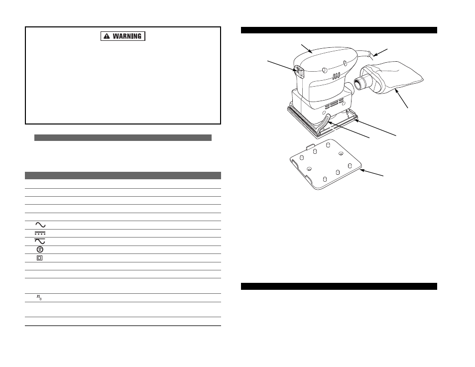
FUNCTIONAL DESCRIPTION
CONTROLS AND COMPONENTS:
1. On/Off Switch
2. Motor Housing
3. Power Cord
4. Dust Collector
5. Bottom Backing Pad
6. Sandpaper Clamp (2)
7. Sandpaper Punch Plate
ASSEMBLY
The Pad Sander is assembled and ready for use. However, if using the Dust
Collection System, the Dust Collector must first be attached the sander.
1. Attach the Dust Collector (bag) to the rear of the Pad Sander. There is a rubber
"O" ring on the Collector nozzle. This maintains a secure fit into the sander.
Turn "OFF" the Pad Sander and disconnect it from the AC power source before
making any adjustments or changing sandpaper sheets.
Keep the handle clean, dry, and free from oil and grease. When cleaning the
Pad Sander, DO NOT use solvents containing carbon tetrachloride or ace-
tone. Never use gasoline, paint thinner, or products containing ammonia. These
chemicals can damage the plastic parts of the tool.
Always wear safety goggles or other approved eye protection when using this
tool. Always use an appropriate dust mask or respirator during operations
where dust can be generated. To reduce exposure to these chemicals always
work in a well ventilated area. Use approved safety equipment and dust masks
that are specially manufactured to filter out microscopic particles.
SYMBOLS
IMPORTANT: Some of the following symbols may be used on your tool. Please
study them and learn their meaning. Proper interpretation of these symbols will
allow you to operate the tool better and safer.
SYMBOL
NAME
EXPLANATION
V
Volts
Voltage (Potential)
A
Amperes
Current
Hz
Hertz
Frequency (Cycles per Second)
W
Watt
Power
Kg
Kilograms
Weight
Alternating Current
Type of Current
Direct Current
Type of Current
Alternating or Direct Current
Type of Current
Earthing Terminal
Grounding Terminal
Class II Construction
Denotes Double Insulation
min
Minutes
Time
s
Seconds
Time
Diameter
Size of Drill Bits,
Grinding Wheels, etc.
No load speed
No-load Rotational Speed
.../min
Revolutions per Minute
Revolutions, Surface Speed,
Strokes, etc. per Minute
1,2,3, …
Ring Selector Settings
Speed, Torque or Position Settings
8
7
FIGURE 1.
PAD SANDER COMPONENTS
7
3
2
1
6
5
4