Kawasaki 840328 User Manual
Page 7
C
CO
ON
NT
TR
RO
OL
L F
FE
EA
AT
TU
UR
RE
ES
S::
A
AS
SS
SE
EM
MB
BL
LY
Y
Always make sure that the power cord is unplugged and the trigger switch is
“OFF” before changing blades or attachments.
W
Wh
he
en
n rre
em
mo
ovviin
ng
g tth
he
e b
blla
ad
de
e ffrro
om
m tth
he
e tto
oo
oll,, a
avvo
oiid
d cco
on
ntta
acctt w
wiitth
h sskkiin
n a
an
nd
d u
usse
e
p
prro
op
pe
err p
prro
otte
eccttiivve
e g
gllo
ovve
ess w
wh
he
en
n g
grra
assp
piin
ng
g tth
he
e b
blla
ad
de
e o
orr a
acccce
esssso
orryy.. Accessories
may be hot after prolonged use.
If the blade clamp screw will not loosen enough to allow
blade installation, tap gently on the end of the wrench with a mallet until the
clamp screw breaks free.
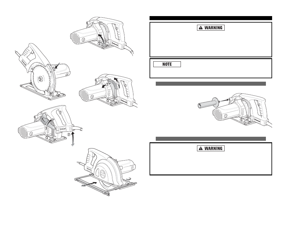
A
AT
TT
TA
AC
CH
HIIN
NG
G A
AU
UX
XIIL
LIIA
AR
RY
Y H
HA
AN
ND
DL
LE
E
This tool comes with an
auxiliary handle which can be
attached to the side of the
circular saw. This handle is
necessary to maintain
complete control of the tool
and should be used at all
times. Make sure this handle
is always fastened securely.
ATTACHING / REMOVING BLADE
Always UNPLUG the power cord before installing or removing blade.
When removing the blade from the tool, avoid contact with skin and use
proper protective gloves when grasping the blade or accessory. Accessories
may be hot after prolonged use.
R
RIIP
P F
FE
EN
NC
CE
E
The scaled rip fence guides the saw to
cut exactly along the edge of work
piece, making straight and
accurate parallel cuts.
D
DE
EP
PT
TH
H
A
AD
DJJU
US
ST
TM
ME
EN
NT
T K
KN
NO
OB
B
This knob controls the
depth of your cut.
R
RIIP
P F
FE
EN
NC
CE
E L
LO
OC
CK
K K
KN
NO
OB
B
This knob secures the rip
fence in place.
H
HA
AN
ND
DL
LE
E A
AD
DJJU
US
ST
TM
ME
EN
NT
T
1. Unplug the power cord. Release
the handle adjustment lock by
pushing the plastic slide in the
direction as shown by the arrows
on the adjustment lock to disen-
gage from the locking pin.
11
12
B
BL
LA
AD
DE
E S
SA
AF
FE
ET
TY
Y
L
LO
OC
CK
K B
BU
UT
TT
TO
ON
N
This button locks the blade in position
and prevents it from moving.
2. Then pull the adjustment lock down so
that it is in parallel with the motor. Now,
raise or lower the handle as desired.
3. Once in the desired position, raise and
push the adjustment lock back to the
handle and ensure it locks inside the pin.