Cs l mode, Batteries, Pc card – Kodak DCS 600 Series User Manual
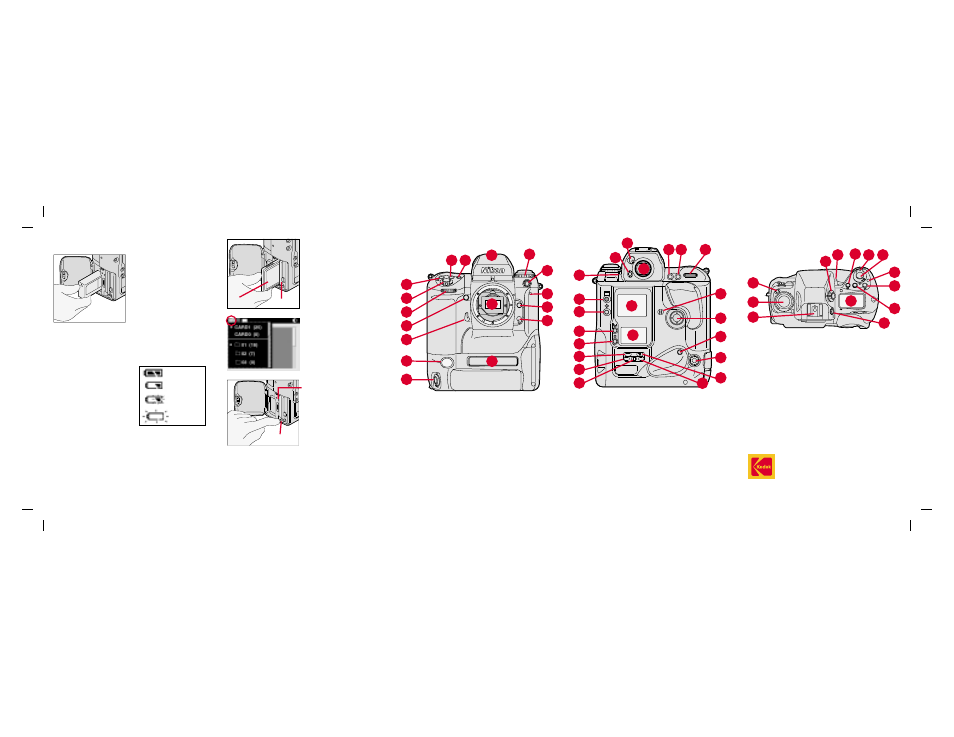
Page 2: Camera front, Camera back, Camera top
L
CSM
BKT
ISO
To insert a PC Card,
open the Battery/PC
Card door and insert.
With two cards, the first
card inserted is the
active card.
To select a different PC
Card, select the Folder
icon, then select the
card. (Refer to other
side.)
Important!
Be sure
the Card Busy LED is
off before removing a
PC Card. The blinking
indicates data is being
transferred to or from
the PC Card. You can lose data if you remove
a PC Card when it is busy.
To remove the PC Card, press the Eject
button.
1. AF Area Mode button
2. Exposure Mode button
3. Exposure Compen-
sation button
4. Shutter Release
5. Sub-Command dial
6. Depth-of-Field Preview
button
7. Mirror Lockup lever
8. White Balance sensor
9. Vertical Shutter release
10. Viewfinder
11. Drive Mode/Self-timer
selector
12. Sync terminal
13. Self-timer LED
14. Lens Release button
15. Focus Mode selector
16. Anti-aliasing filter (IR filter
in DCS 660M or DCS
620 base camera)
17. Product label
EASTMAN KODAK COMPANY
Rochester, New York 14650
© Eastman Kodak Company, 2000
Kodak and Kodak Professional are trademarks.
Printed in U.S.A.
P/N 6B5235
5/00
Batteries
To power your camera,
open the Battery/PC
Card door, slide a
battery to the back of
the battery slot and
press firmly in place.
☛
You can also power your camera with an
AC adapter when working indoors or
connected to a computer.
Check the battery icon
on the Back Status
LCD panel.
Full
Low
Insufficient
Empty
PC Card
As you capture images, they are stored on
Type II or Type III PC Cards (PCMCIA cards)
in your camera.
There are two slots for PC Cards. You can
insert two Type II cards or one Type III card.
Card 1
Card 0
Eject button
Camera
Front
1
2
3
4
5
6
7
8
9
10
11
12
13
14
15
16
17
Camera
Back
1
2
3
4
5
6
7
8
9
10
11
12
13
14 15
16
17
18
19
20
21
22
1. Eyepiece Shutter lever
2. Finder Release button
3. Alert LED
4. Image LCD panel
5. Display button
6. Selector button
7. Record/Tag button
8. White Balance button
9. Back Status LCD panel
10. ISO button
11. Auto Exposure/Flash
Exposure Bracketing
button
12. Shutter Speed/Aperture/
Focus Area Lock button
13. Viewfinder eyepiece
14. Auto Exposure/Autofocus
Lock button
15. AF Start/AF On button
16. Main-Command dial
17. Microphone
18. Navigate switch
19. Vertical AF Start button
20. Remote Release port
21. Flash Sync Mode button
22. Custom Setting Menu
button
C
S
L
MODE
O
O
F
N
F
Camera Top
1
2
3
4
5
6
7
8
9 10
11
12
13
1. Metering System
Selector lock release
2. Metering System
Selector
3. Drive Mode Selector lock
release
4. Drive Mode/Self-timer
selector
5. Accessory Shoe
6. Diopter Adjustment knob
7. Top Status LCD panel
8. AF Area Mode button
9. Power/LCD Panel
Illumination switch
10. Shutter Release button
11. Power Switch lock
release
12. Exposure Compensation
button
13. Exposure Mode button