Controls – Southbend SB1041 User Manual
Page 25
For Machines Mfg. Since 8/09
Model SB1040/SB1041
-23-
O P E R A T I O N
Controls
Refer to Figures 10–12 and the following
descriptions to become familiar with the basic
controls of this machine.
A.
Motor
Light:
Lights when the ON button is
pressed and there is power to the machine.
B.
ON
Button:
Turns the main motor ON.
C
.
OFF
Button:
Turns the main motor OFF.
D.
Clamping Pressure Dial:
Sets the correct
amount of pressure for pressing the ends of
the blades against each other when welding.
E.
Welding
Clamp:
Holds a segment of the
bandsaw blade to be welded.
F.
Lock
Lever:
Secures bandsaw blade for
welding operations when rotated up.
G.
Grinder
Switch:
Turns grinder ON/OFF.
H.
Shear
Lever:
Cuts the bandsaw blade.
I.
Welding
Button:
Activates the process of
fusing the two blades together.
J.
Annealing
Button:
Heats up the blade joint,
then allows it to cool in a gradual manner to
establish weld strength.
K.
Blade Speed Display:
Displays the current
blade speed in Feet Per Minute (FPM).
Figure 10. Front controls.
J
K
L
A
I
H
G
F
B
C
D
E
L.
Welder's Lamp Switch:
Illuminates
welding station when turned ON.
M.
Variable Speed Handwheel:
Adjusts blade
speed from 88 to 384 FPM.
Figure 11. Variable speed handwheel.
M
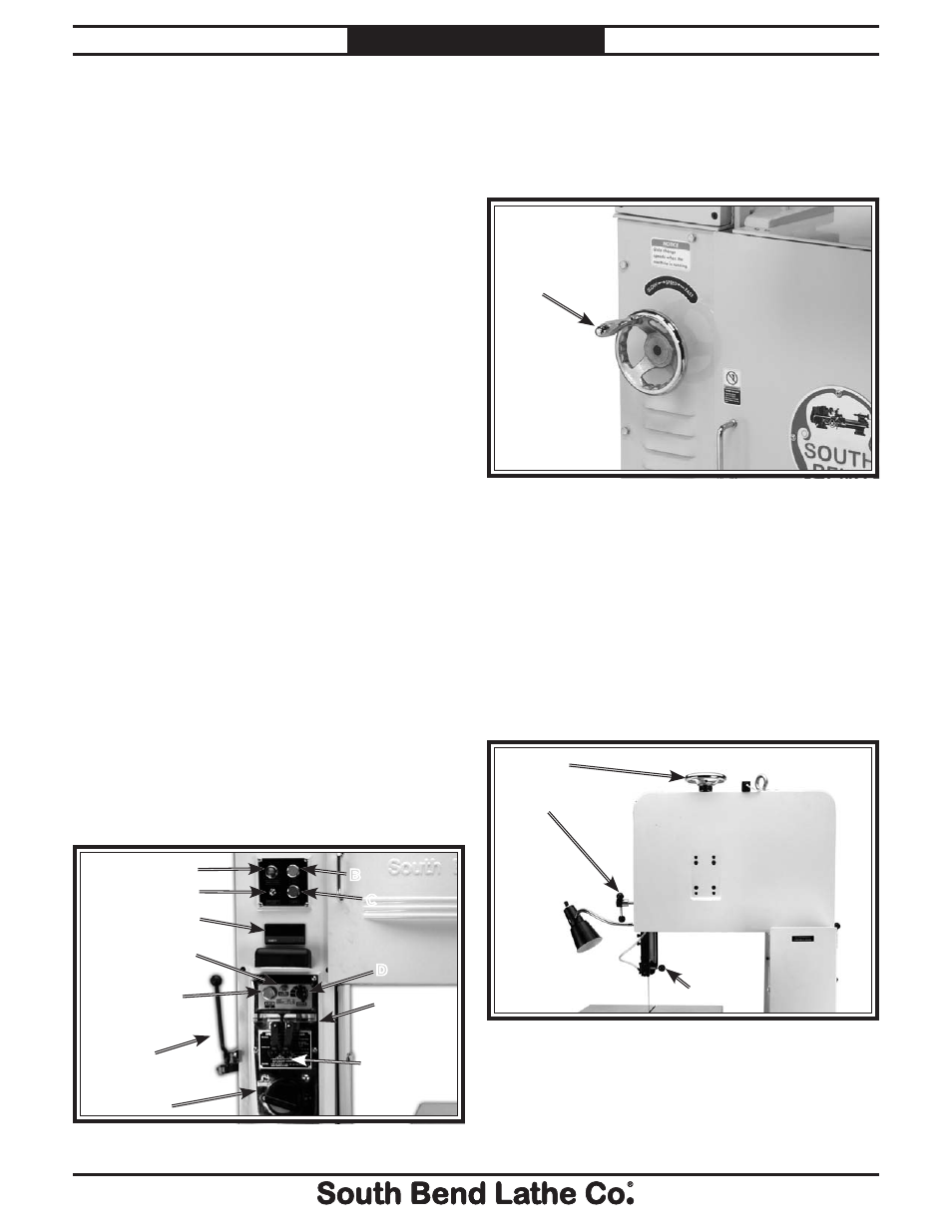
N.
Blade Tensioning Handwheel:
Increases or
decreases blade tension when rotated.
O.
Guide Post Elevation Knob:
Raises or
lowers the guide post and upper blade guide
assembly.
P.
Guide Post Lock Knob:
Secures the guide
post and upper blade guide assembly in
position.
Figure 12. Blade controls.
N
O
P