Receiver setup 6, Step3: basic operations, 7receiver setup (cont) – Swann ADW-300 User Manual
Page 6
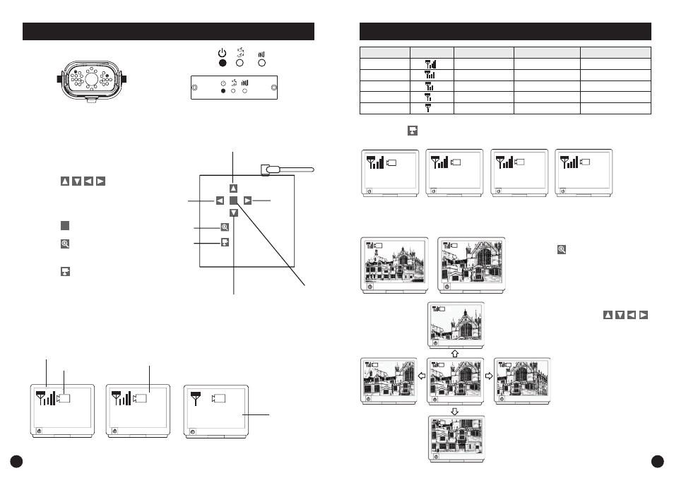
Receiver Setup
6
Wireless Connection LED Indicator
When wireless signal is well connected, LED indicators as shown:
Step3: Basic Operations
Receiver Control Panel
1. Pressing
(Up / Down /
Left / Right), In Zoom IN mode (ZOOM),
pan and tilt the camera
In the OSD menu, move between the
selections
2. Pressing
M
(OSD menu),Enter / Exit
OSD menu Mode
3. Pressing
(Zoom IN / OUT),Zoom
IN (ZOOM, QVGA size) or Zoom OUT
(VGA size) the camera
4. Pressing
(Cam / Pair)
In View mode, manually select among
available camera channels
In Pair mode, assign and pair private
camera to specified channel
M
Up
Left
Zoom
Camera
Select/
Pair (Pair
mode)
Down
Menu
Right
1
1
1
Zoom
Signal Indicator
Channel Indicator
Zoom Indicator
Status Indicator
No Connection
A. Signal Indicator shows signal strength, more bars means stronger signal.
In the View Mode
7
Receiver Setup (cont)
Signal Level
Indicator
Data Rate
VGA Frame Rate
QVGA Frame rate
Perfect
1062~1280Kbps
5~10Fps
15~30Fps
Good
725~1062Kbps
3~5Fps
12~20Fps
Fair
543~725Kbps
2~4Fps
8~15Fps
Low
250~543Kbps
0~1Fps
0~4Fps
Zero
0~250Kbps
0Fps
0Fps
1
2
3
4
B. Channel indicator shows the current camera been picked up by the receiver
By pressing
(Cam), you can manually switch among multi cameras.
Or you can set up auto scan in the OSD menu.
Camera 1
Camera 2
Camera 3
Camera 4
C. When System Message shows “NO Connection”, it means Service out of Range.
Please refer to the Troubleshooting guide on page 10.
1
ZOOM
1
ZOOM
1
ZOOM
1
ZOOM
1
ZOOM
1
ZOOM
1
D. Zoom Indicator shows Zoom status
By pressing
(Zoom) on the receiver,
you can switch between two resolutions.
E. Pan / Tilts
In Zoom IN mode (ZOOM), press
to pan and tilt camera view.