Figure 8. spindle sync diagram – Seagate BARRACUDA2 User Manual
Page 28
26
ST12450W/WD Installation Guide, Rev. B
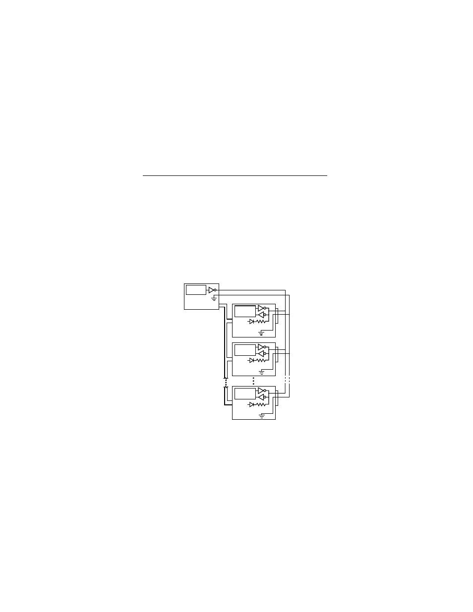
Figure 8 illustrates a typical synchronized spindle
configuration.
After connecting each drive with spindle sync cables,
you must designate a master spindle sync reference
source. This master source is normally a disc drive
located on the same SCSI bus as the other drives you
want to synchronize with. To designate a drive as the
master, use SCSI interface commands. Refer to the
product manual for information about using these
commands.
Figure 8. Spindle sync diagram
Master Sync
Source
Host
(or other drive)
Spindle
Control
Drive 1
+5V
RT
J5
11
12
Spindle
Control
Drive 2
+5V
RT
J5
11
12
Spindle
Control
Drive n
+5V
RT
J5
11
12
Sync Interface
System
Interface
This manual is related to the following products: