Step 7: hydraulic relief pressure setting, Step 8: cable control installation – Stellar Industries SI-60 User Manual
Page 36
30
Stellar Cable Hoist Owner’s Manual
Step 8: Cable Control Installation
The standard cable controls supplied with Stellar equipment are high-quality assembly
which seal out moisture, are corrosion protected, and engineered to minimize backlash
(lost motion). After the hoist and hydraulic tank are mounted to the truck chassis, the
remote cable controls may be installed.
Cable Control Mounting:
1. On the hydraulic control valve, remove the screws holding the spool cover plate.
Position the handle assembly on the valve face and install the screws provided with the
handle kit. Install the clevis pin and cotter pin.
2. Mount the valve to the underside of the mounting plate located on the top of the
hydraulic tank assembly with the handles sticking up through the rectangular cutout.
3. Position the control cable bulkhead plate on the top of the hydraulic tank assembly.
Install the control cable bulkhead plate with 1/2” cap screws and nuts, or weld. If nec-
essary, temporarily assemble the threaded cable end to the bulkhead plate for proper
positioning with the valve handles.
4. Mount the cable controllers to the
control mount supplied. Other
mounting options are shown in the
following illustration (parts not sup-
plied).
Important:
a. A good cable path is essential
for a properly operating sys-
tem. Keep bends in the cable
path to a minimum and as
generous as possible. Under no circumstances should any bend be tighter than
an 8” radius.
b. Protect the cable from heat above 225ºF and avoid hot areas such as the
exhaust system, etc.
c. Protect the cable from physical damage such as pinching or crushing and do
not use cable supports which may crush or deform the cable.
d. Allow room for flexing where the cable is attached to moving parts of the equip-
ment so that the cable is neither kinked nor stretched.
Flush
Mounting
Side
Mounting
Banked
Together
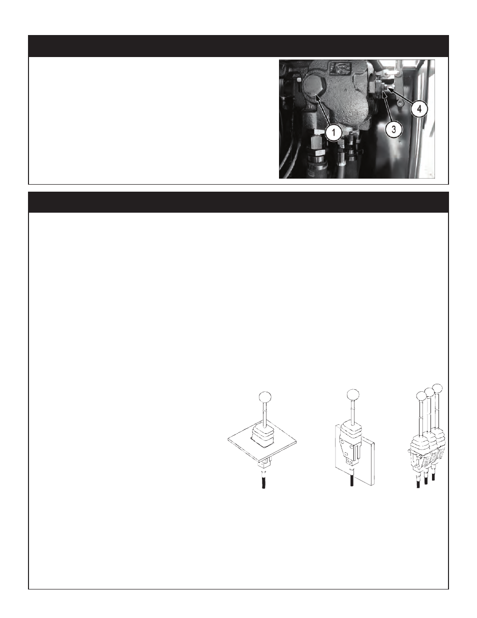
1. Locate the pressure gauge facing front of truck.
2. Loosen Jam Nut.
3. Using allen wrench, adjust to proper pressure. See
Chapter 4: Specifications for pressure specifica-
tions.
4. Tighten Jam Nut, holding adjustment screw in posi-
tion.
5. Test unit for proper operation, readjust to correct
pressure if needed.
6. Retest unit checking leaks and proper operation.
Step 7: Hydraulic Relief Pressure Setting