Step 3: mount lift cylinders, Figure a, Figure b – Stellar Industries SI-60 User Manual
Page 33: 27 installation 27
27
Installation 27
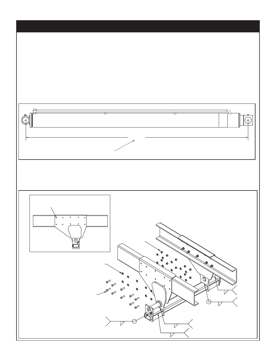
Step 3: Mount Lift Cylinders
A. Check frame for bolts, rivets, etc. and clearance required (Refer to the previous
pages) before placing the Lift Cylinder Weldment into place under the hoist sub-frame.
B. Install the cylinder weldment cross tube.
C. Install the Lift Cylinders and extend each cylinder rod 1/4”. Check the shaft to cylinder
dimension on both sides. Standard Lift Cylinders dimension should be 88 1/4” plus or
minus1/8”. Telescopic Cylinder dimension should be 61-1/4” plus or minus 1/8”. Be sure
to install proper cylinder shaft hardware so that Lift Cylinders do not interfere with truck
frame or bolts. The lift cylinders will precisely locate the lift cylinder weldments.
D. Clamp the Lift Cylinder Weldment in place and drill ten (10) 11/16” diameter holes as
per Figure B.
90.00 ±.13
DIMENSION WHEN INSTALLING.
ACTUAL RETRACTED DIMENSION IS 88"
Figure A
TRUCK FRAME
TRUCK FRAME
TYPICAL BOLT HOLE PATTERN
MOUNTING KIT - BOLTED ON
11/16" DIAMETER DRILL
PN C5902
WASHER 0.63 SAE
FLAT YELLOW GR8
CAP SCR 0.63-11X2.50
HHGR8
PN C1026
PN 24868
NUT 0.63-11
HHGR8 NYLOC
0.25
TYP 2
0.25
TYP 4
0.25
TYP 2
Figure B
0.25
TYP. 4
0.19
1.00
TYP. 4