Truck chassis specifications, Step 1: truck frame cut-off – Stellar Industries SI-60 User Manual
Page 28
22
Stellar Cable Hoist Owner’s Manual
Measure and mark the truck frame as shown below. Use the dimensional drawings on
the following pages to determine where to mark the first vertical cut on the frame rail.
Measure assembled hoist to be sure that adequate room is available behind truck cab;
between bumper and tires; and between fender and tires. This verifies that a measure-
ment error has not been made either in the CT (Cab to Trunnion) or cut-off dimension.
After double checking your measurements, step-cut the truck frame as shown below.
See the illustrations on pages 15-17 at the front of this manual for specific details.
1. Thoroughly check the truck requirements to ensure proper clearance and frame
strength before mounting the hoist. Note: The rear cab boundary is the rearmost
unremovable protrusion behind the cab and above the chassis frame.
2. The CT, from the rear of the cab boundary to the center of the walking beam suspen-
sion, is shown in the table below:
Minimum Axle Rating:
Front: 18,000 lbs.
Rear: 44,000 lbs. with walking beam type suspension
Frame Strength:
Total RBM per frame rail = 2,400,000 in-lbs. (both channels)
Section Modulus (minimum) = 32 in
3
for 36,000 PSI steel
Section Modulus (minimum) = 24 in
3
for 55,000 PSI steel
Important: If your truck chassis height exceeds the 45” dimension, or tire dimension is
greater than 102”, the O.R.X. or I.O.X. hoist should be considered.
Relocate the rear axles as required.
Stellar Autotarper must have 10”
to 12” unobstructed space behind
cab for installation.
Model
Cab to Trunnion
w/o Tarper
With Tarper
SI60-174 174 Inches
180 Inches
SI60-182 182 Inches
188 Inches
SI60-194 194 Inches
200 Inches
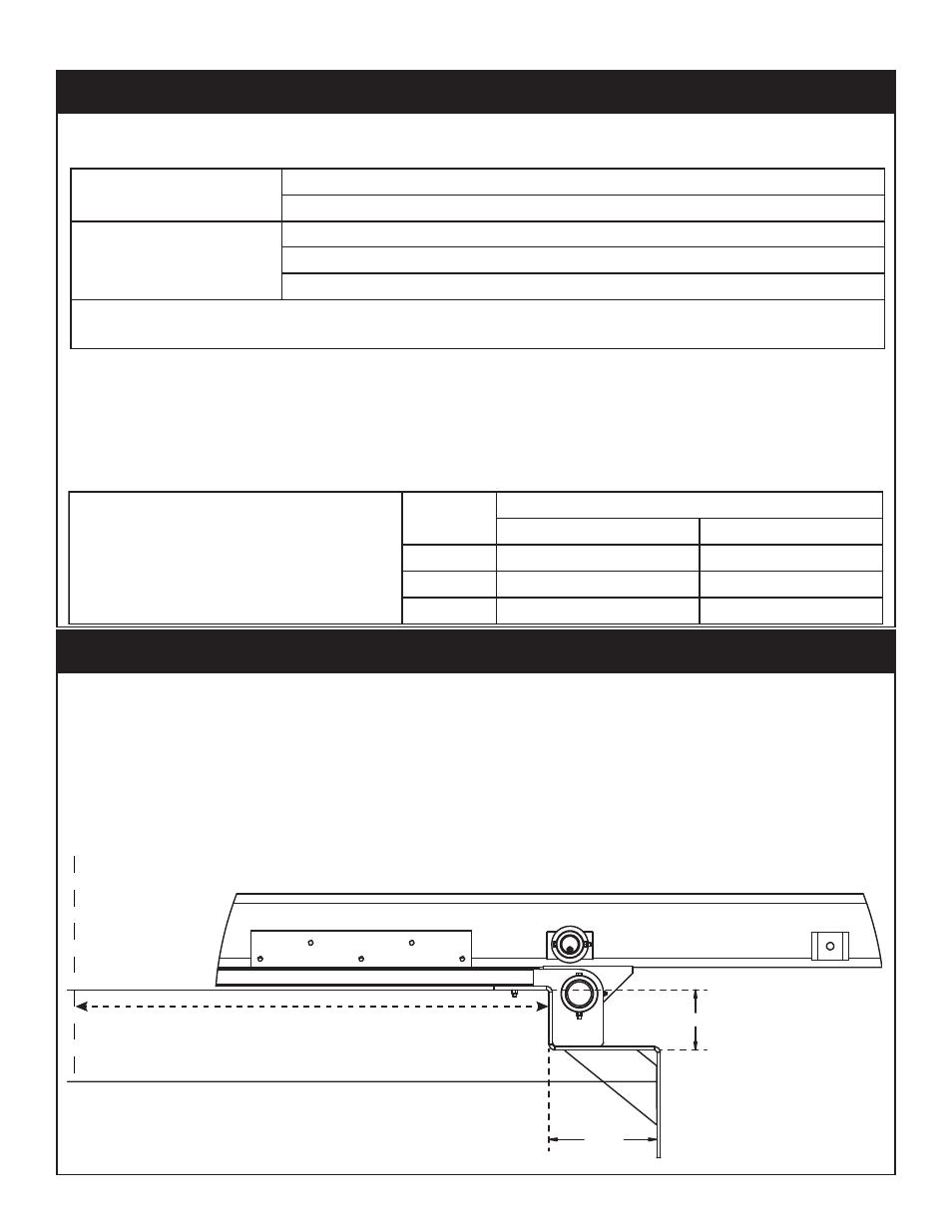
Step 1: Truck Frame Cut-Off
6-9/16
FRAME RAIL
11-3/4
Cab Boundary
Refer to dimensional drawings on the following pages
for placement of step cut in relation to cab boundary.
Truck Chassis Specifications