Engine and frame group – Simplicity 1694914 User Manual
Page 14
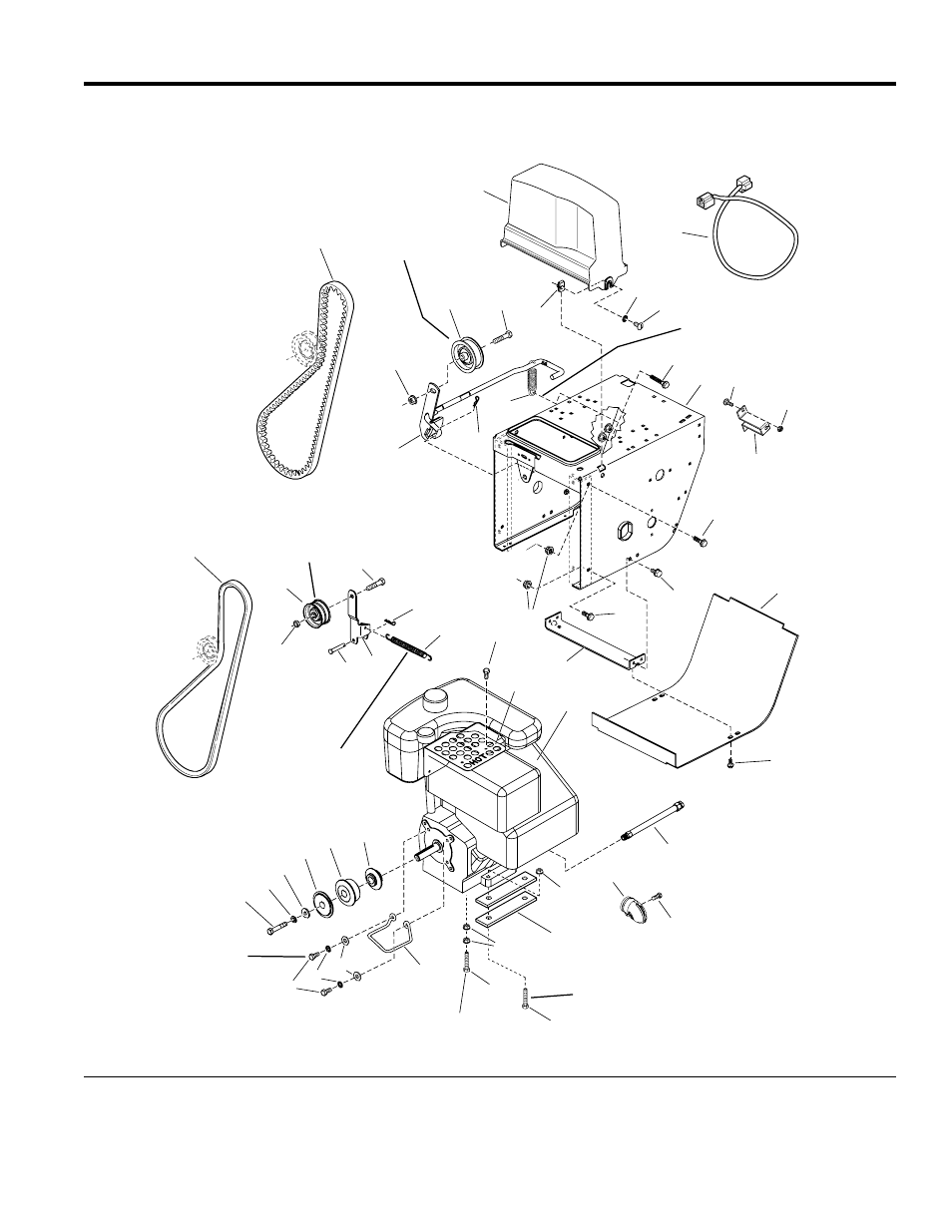
Engine and Frame Group
NOTE: Unless noted otherwise,
use the standard hardware torque
specification chart.
Hook one end of spring (Ref. 7)
into top hole of roller arm (Ref. 6)
and other end into top hole of the idler
arm assembly in the Traction Drive Group.
Long hub of idler
pulley (Ref. 3) to
be toward idler
arm (Ref. 6).
Position idler pulley (Ref. 12)
at center of slot in clutch arm
(Ref. 10).
Hook one end of spring (Ref. 14)
over clutch rod assembly (Ref. 10)
between tabs and other end onto
the tube handle capscrew (Ref. 20).
Torque (4) Engine
Bolts to 17 - 21 ft. lbs.
or 23 - 29 N m
Torque to
10-14 ft. lbs. or
14-20 N m
Right rear bolt.
1
9
15
16
17
18
21
20
25
26
27
28
29
14
30
7
6
5
2
3
4
8
8
10
11
12
13
14
39
29
48
49
50
25
37
19
22
24
23
38
40
37
41
45
46
47
35
42
35
43
35
44
31
32
34
36
35
33
987035
The above parts group applies to the following Mfg. Nos.:
2005
14
© Copyright Simplicity Manufacturing, Inc. All Rights Reserved.
1694867 - 9560E
1694914 - 9560EX
TP 400-4250-00-LW-S