Shure SM81 User Manual
Page 2
2
Maximum SPL (at 1,000 Hz)
800 Ω load: . . . . . . . . . . . . . . . . . . . . . 136 dB (attenuator at 0)
146 dB (attenuator at -10)
150 Ω load: . . . . . . . . . . . . . . . . . . . . . 128 dB (attenuator at 0)
138 dB (attenuator at -10)
Hum Pickup
-3 dB equivalent SPL in a 1 mOe field (60 Hz)
Self-Noise (equivalent sound pressure levels; measured with true
rms voltmeter)
16 dB typical, A-weighted
19 dB typical, weighted per DIN 45 405
Signal-to-Noise Ratio
78 dB (IEC 651)* at 94 dB SPL
*S/N ratio is difference between microphone output at 94 dB SPL and
microphone self-noise A-weighted.
Overvoltage and Reverse Polarity Protection
Max. external voltage applied to pins 2 and 3
with respect to pin 1: . . . . . . . . . . . . . . . . . . . . . . . . . +52 Vdc
Reverse polarity protection: . . . . . . . . . . . . . . . . 200 mA max.
(diode-clamped)
Polarity
Positive pressure on diaphragm produces positive voltage on
pin 2 relative to pin 3
Cartridge Capacitance
54 pF
Low Frequency Response Switch Positions
Flat; -6 dB/octave below 100 Hz; -18 dB/octave below 80 Hz
Attenuator Switch Positions (Lockable)
0 or -10 dB
Power
Supply Voltage:. . . . . . . . . 11 to 52 Vdc, positive, pins 2 and 3
Current Drain: . . . . . . . . . . . . . . . . . . . . . . . . . . . . 1.2 mA max.
Environmental Conditions
Temperature
Storage: . . . . . . . . . . . . . . . . . . . . . . . . . . . . . –29° to 74° C
(–20° to 165° F)
Operating:. . . . . . . . . . . . . . . . . . . . . . . . . . . . –6.7° to 49° C
(20° to 120° F)
Humidity
Storage: . . . . . . . . . . . . . . 0–95% relative humidity at room
temperature (72° to 80° F, 22° to 27° C)
Case
Steel construction with vinyl metallic paint finish and stainless
steel screens
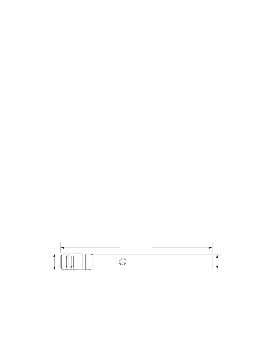
Dimensions
See Figure 3
Weight
Net: . . . . . . . . . . . . . . . . . . . . . . . . . . . . . . . . 230 grams (8 oz)
Packaged: . . . . . . . . . . . . . . . . . . . . . . . 740 grams (1 lb 10 oz)
Certification
Eligible to bear CE marking. Conforms to European EMC Direc-
tive 89/336/EEC. Meets applicable tests and performance cri-
teria in European EMC Standard EN 55103 (1996) parts 1 and
2 for residential (E1) and light industrial (E2) environments.
OPERATION
Power
The SM81 requires phantom power. This may be supplied to the
microphone by a mixer, preamplifier or console with built-in phan-
tom power or from an external power supply (such as the Shure
model PS1A). Phantom power sources providing between 11 and
52 Vdc are suitable.
Use only high-quality cables because intermittent shorts be-
tween broken shield wires and balanced conductors will cause ex-
tremely large noise transients in the system. Avoid ground loops
due to grounded connector shells or the microphone case touching
other grounded metal objects. Follow generally accepted audio
grounding practices.
Impedance
A minimum load impedance of 800 Ω or greater should be used
for maximum signal handling and minimum distortion. The load
may be as low as 150 Ω, but a reduction in output clipping level will
result. It should be noted that the power supply itself may add load-
ing (3300 Ω in the Shure PS1A power supply) to the microphones.
PS1A Power Supply
When using the Shure PS1A to phantom power the SM81, con-
nect the microphone cable to the SM81 and to the MICROPHONE
connector of the power supply. The power supply uses the bal-
anced audio cable pair to carry the supply current to the micro-
phone and the cable shield as a ground return.
Connect the OUTPUT connector of the power supply to a
low-impedance microphone input of a mixer, audio console or tape
recorder. A second SM81 may be connected to the remaining pow-
er supply channel in a similar manner.
OVERALL DIMENSIONS
FIGURE 3
212 mm
20 mm
23.5 mm