Solid State Logic Super-Analogue Outboard X-Rack E Series User Manual
Page 8
Page K-6
X-Rack Owner’s Manual
4. Switch BLK in and re-adjust LMF Frequency for maximum level.
5. Adjust VR16 for +18dBu ±0.25dB.
6. Reset LMF Gain to its centre indent position and release the BLK switch.
Re-check the audio level meter for 0dBu.
LF EQ – Maximum Gain
Adjustment:
1. Ensure that the BLK switch is released.
2. Set LF Gain to maximum and select LF BELL. Set the audio oscillator for
80Hz and adjust LF Frequency to find the maximum level on the audio
level meter.
3. Adjust VR17 for +15dBu ±0.25dB.
4. Switch BLK in and re-adjust LF Frequency for maximum level.
5. Adjust VR18 for +18dBu ±0.25dB.
6. Reset LF Gain to its centre indent position, release the BLK switch and de-
select LF BELL. Re-check the audio level meter for 0dBu.
K.4.2 Output Balance
Equipment Required:
Calibrated audio oscillator, audio level meter and a ‘balance’ adaptor (see
below).
Test Signal:
1kHz sine wave at +24dBu.
Input and Output:
Oscillator to the Input of the channel being tested, Output to the level
meter via the ‘balance’ adaptor.
Unit Setup:
Ensure that all front panel switches are off and all controls are set fully
anti-clockwise.
Adjustment:
Connect the test equipment to the each channel in turn and adjust VR19
(BAL) for minimum level (< 55dBr).
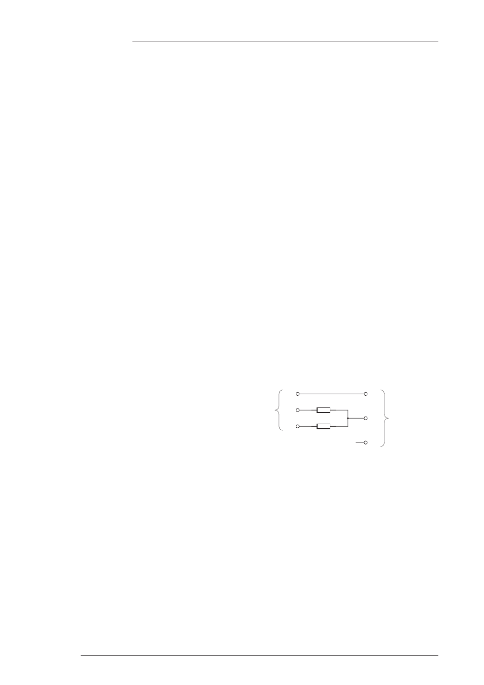
K.4.3 ‘Balance’ Adaptor
For the output balance adjustment, a ‘balance’
adaptor such as that illustrated here will be
required. This adaptor consists of a pair of
close tolerance resistors in an in-line cable and
is used to sum together a balanced output in
order to correctly adjust the level balance of the
measured output; perfect balance should result
in complete signal cancellation.
5K01**
5K01**
2
3
1
2
3
1
0V
+
–
0V
+
–
To measuring
equipment
From unit
under test
1
2
1
Resistor tolerance should ideally be 0.01%
Absolute level measured will depend upon the input
impedence of the measuring equipment.
1.
2.
Note