Connectors and plug-ins – SOYO SY-K7VEMPRO V1.0 User Manual
Page 11
SY-K7VEMPRO V1.0 Quick Start Guide
11
Har
dw
ar
e
Install
atio
n
Step 3.
Connections to the Motherboard
This section tells how to connect internal peripherals and the power supply to the
Motherboard.
The internal peripherals consist of IDE devices (HDD, CD-ROM), Floppy Disk Drive,
Chassis Fan, Front Panel Devices (Internal Speaker, Reset Button and IDE LED Switch.),
Wake-On-LAN card, VGA card, Sound Card, and other devices.
For more details on connecting internal and external peripherals to your new
SY-K7VEMPRO V1.0 Motherboard, please refer to SY-K7VEMPRO V1.0 Motherboard
User's Guide and Technical Reference online manual on the CD-ROM.
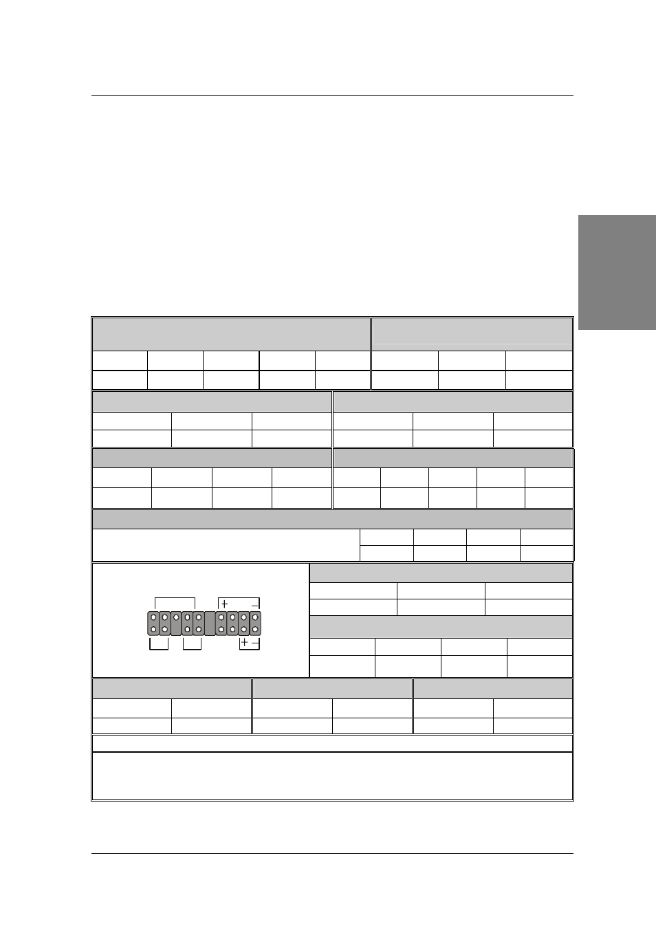
Connectors and Plug-ins
Standard IrDA (Infrared Device Header):
SIRCON1
Wake-On-LAN Header: JP44
Pin1 Pin2 Pin3 Pin4 Pin5
Pin1 Pin2 Pin3
VCC NC IRRX GND IRTX
5VSB GND Wakeup
CPU Cooling Fan: CPUFAN1
Chipset Fan: CHIPFAN
Pin1 Pin2 Pin3 Pin1 Pin2 Pin3
GND 12V
SENSOR
GND 12V NC
USB3
USB4
Pin1
Pin2
Pin3
Pin4
Pin6
Pin7
Pin8
Pin9
Pin10
Power
Data(-)
Data(+)
GND
Power Data(-) Data(+)
GND
GND
CD Line-in: CDIN1
Pin 1
Pin 2
Pin 3
Pin 4
Connect the CD Line-in cord from the CD-ROM device to
the matching header CDIN1
L G G R
Power LED / ACPI LED
Pin1 Pin2 Pin3
Control NC GND
Speaker
Pin1 Pin2 Pin3 Pin4
5V NC NC
Speaker
out
HDD LED
PWRBT
RESET
Pin1 Pin2 Pin1 Pin2 Pin1 Pin2
LED Anode
LED Cathode Power On/Off
GND
Control
GND
ATX POWER On/Off : PWRBT
Connect your power switch to this header (momentary switch type).
To turn off the system, please press this switch and hold down for longer than
4 seconds.
Speaker
Power / ACPI LED
HDD LED
_
+
Reset PWRBT