Installation, Inspection, Requirements – Schneider Electric DuraDrive Direct Coupled Actuators MA4X-707X User Manual
Page 7: Installation inspection
F-26642-8
© Copyright 2010 Schneider Electric All Rights Reserved.
7
INSTALLATION
Inspection
Inspect the package for damage. If damaged, notify the appropriate carrier immediately. If
undamaged, open the package and inspect the device for obvious damage. Return
damaged products.
Requirements
•
Job wiring diagrams
•
Tools (not provided):
– #8 sheet metal screws
– 10mm open end wrench or socket wrench
– 7/16 inch, open end wrench or socket wrench
– 1/8 inch, allen wrench
– Appropriate screwdriver(s)
•
Appropriate accessories
•
Training: Installer must be a qualified, experienced technician
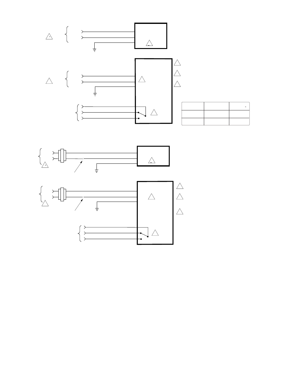
MA40-7040
MA40-7041
MA40-7040-501
MA40-7041-501
120 Vac or
230 Vac
Wire No. 1
Wire No. 2
Neutral
Hot
2
2
Wire No. 2
Wire No. 1 Neutral
Hot
L1 N
L2 H
L1 N
L2 H
1
1
3
Orange
Violet
Yellow
N.C.
COM.
N.O.
Auxiliary Switch 1
1 Provide overload protection and disconnect as
required.
2 Actuators may be wired in parallel. Power
consumption must be observed.
3 For end position indication, interlock control, fan
startup, etc., MA40-704X-501 model incorporates
one built-in auxiliary switch. See Specifications
section for details.
120 Vac or
230 Vac
Green/Yellow
Green/Yellow
Voltage
Wire 1
Wire 2
120 Vac
White
Black
230 Vac
Light Blue
Brown
0 to 1 Scale
Adjustable
Figure-2 Typical Wiring Diagram for 120 Vac or 230 Vac Basic and Single Auxiliary Switch Models.
MA40-7043
MA40-7043-501
24 Vac
2
2
Red
Black
Common
Hot
1
1
(1)
(2)
3
Orange
Violet
Yellow
N.C.
N.O.
Auxiliary Switch 1
Line
Volts
1 Provide overload protection and disconnect as
required.
2 Actuators may be wired in parallel. Power
consumption must be observed. Actuator may also
be powered by 24 Vdc.
3 For end position indication, interlock control, fan
startup, etc., MA40-7043-501 model incorporates
one built-in auxiliary switch. See Specifications
section for details.
24 Vac
Black
Red
Common
Hot
Line
Volts
SPST Control Contact
SPST Control Contact
Green/Yellow
Green/Yellow
0 to 1 Scale
Adjustable
Figure-3 Typical Wiring Diagram for 24 Vac Basic and Single Auxiliary Switch Models.