Scraper bar & skid shoe adjustment, Intermediate frame snowthrowers – Simplicity SMI I1924E User Manual
Page 14
Intermediate Frame Snowthrowers
TP 300-4681-01-IW-SN
09/2007
14
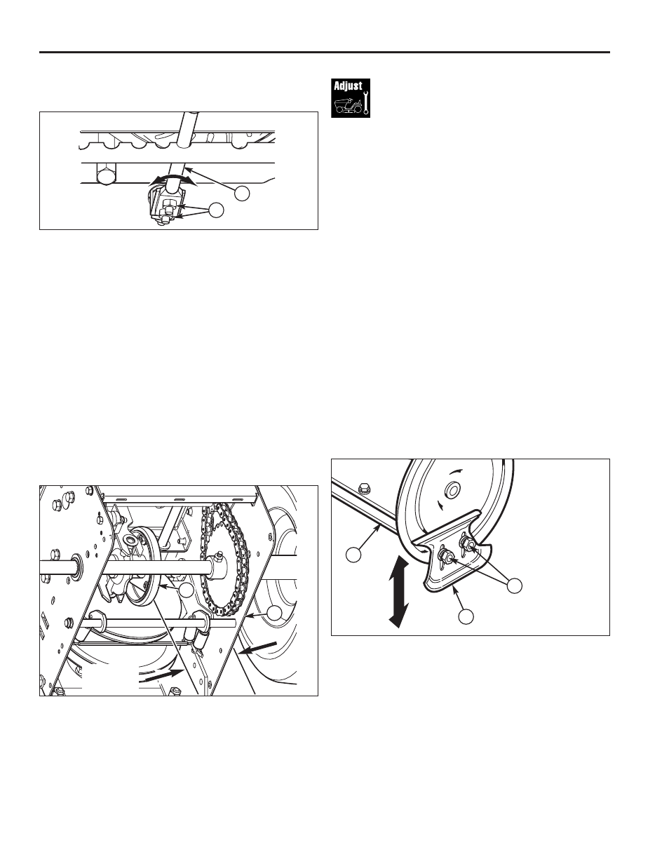
Figure 8. Skid Shoe Adjustment
A. Scraper Bar
B. Skid Shoe
C. Nuts
A
B
C
On smooth surfaces such as concrete or asphalt, the
scraper bar should scrape the surface. On surfaces such
as gravel, the scraper bar should be high enough so that
it will not pick up gravel or debris.
The height of the scraper bar is controlled by raising or
lowering the Skid Shoes (See Figure 8).
1. To raise the scraper bar height, rest the scraper bar on
a strip of wood equal in thickness to the desired height.
2. Make sure the scraper bar is parallel to the ground
surface.
3. Loosen the skid shoe nuts and let the skid shoes drop
to the surface.
4. Tighten the nuts, making sure the Skid Shoes are
adjusted equally and are parallel to the surface.
5. To lower the height of the scraper bar, raise the Skid
Shoes.
6. If the scraper bar becomes worn, it can be adjusted
by loosening the nuts and bolts attaching it to the
snowthrower, making the adjustment, and tightening
the hardware. It may also be replaced by removing
the mounting nuts and bolts attaching it to the
snowthrower.
Scraper Bar &
Skid Shoe Adjustment
7. Loosen shift lever nuts (B, Figure 6), and position the
shift speed lever (A) in the lowest forward speed.
Figure 6. Shift Lever Adjustment
A. Shift Lever
B. Nuts, 1/4-20
A
Figure 7. Friction Disc Measurement
A. Friction Wheel
B. Frame
4-5/16”
(10.95cm)
8. Note the position of the friction wheel (A, Figure 7).
The correct distance from the right side of the friction
wheel to the outside of the frame is 4-5/16” (10.95
cm). If the friction wheel is not in the correct position,
adjust as follows.
9. Move the friction wheel (A, Figure 7) to the correct
distance, 4-5/16” (10.95 cm).
10. Tighten the 1/4-20 shift lever nuts (B, Figure 6) to 60
lb-in. (6,8 Nm).
11. Check that the snowthrower operates in R1. If not
follow procedures 1-10 and readjust as necessary.
12. Install the bottom panel (B, Figure 5) and tighten the
capscrews (A).
A
B
B