Appendix c—typical phase noise plots, Figure 67. 155.52 mhz in; 622.08 mhz out, Si53xx-rm – Silicon Laboratories SI5375 User Manual
Page 119
Si53xx-RM
Rev. 1.2
119
A
PPENDIX
C—T
YPICAL
P
HASE
N
OISE
P
LOTS
Introduction
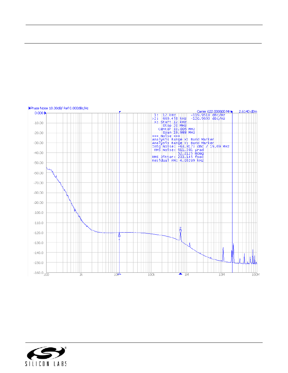
The following are some typical phase noise plots. The clock input source is a Rohde and Schwarz model SML03
RF Generator. Except as noted, the phase noise analysis equipment is the Agilent E5052B. Also (except as noted),
the Any-Frequency part was an Si5326 operating at 3.3 V with an ac-coupled differential PECL output and an ac-
coupled differential sine wave input from the RF generator at 0 dBm. Note that, as with any PLL, the output jitter
that is below the loop bandwidth of the Any-Frequency device is caused by the jitter of the input clock, not the Any-
Frequency Precision Clock. Except as noted, the loop bandwidths were 60 Hz to 100 Hz.
Figure 67. 155.52 MHz In; 622.08 MHz Out