Specifications, Install the wand holders, Introduction – Shindaiwa 80702 User Manual
Page 2: Install the shaft, Prepare to assemble
2
This manual contains information for the proper assembly,
operation and care of your SP518 sprayer. Carefully read and
follow the instructions contained in this manual before operat-
ing your sprayer.
Specifications
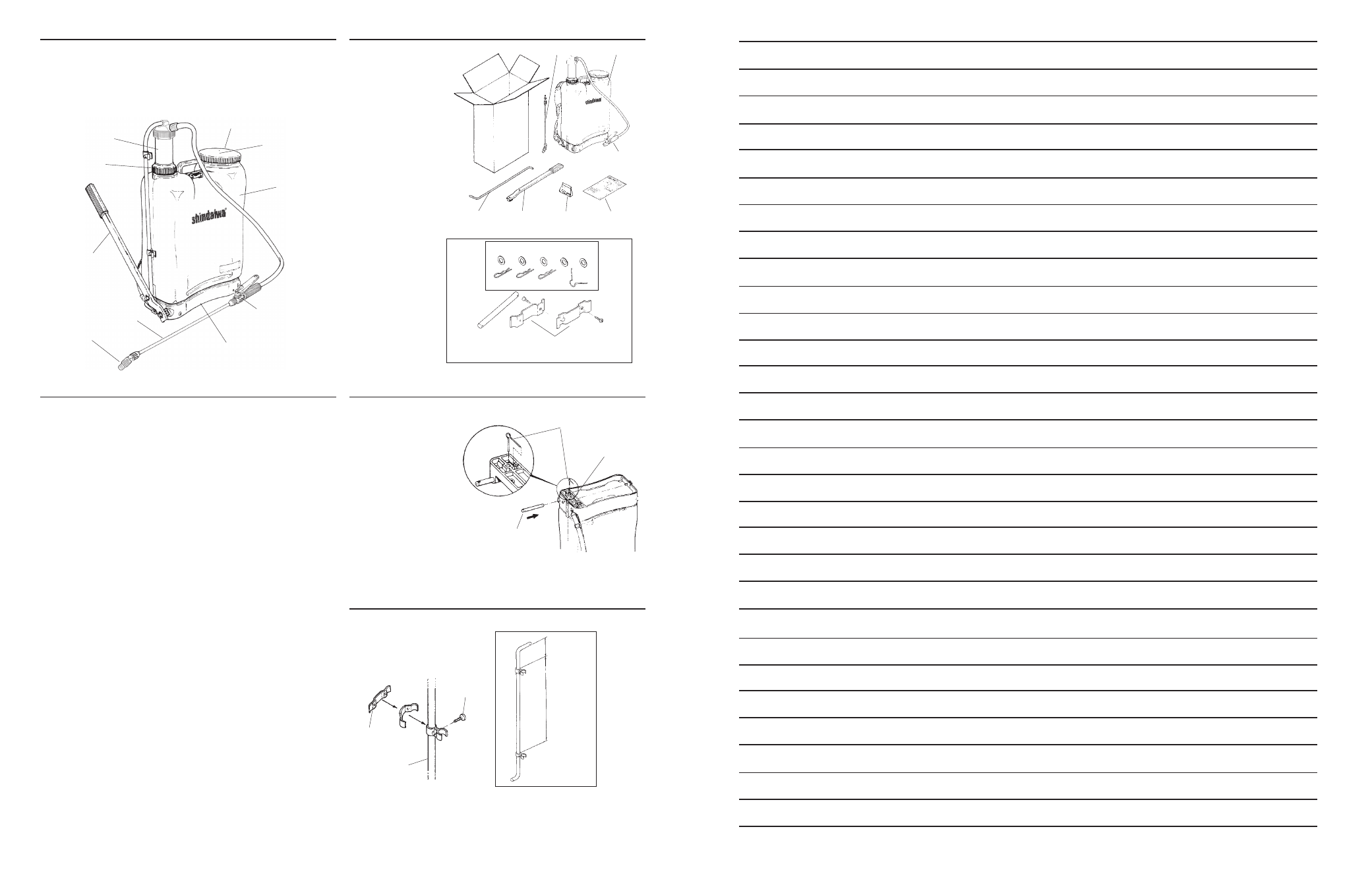
Unpack the following
items shipped in
your sprayer box:
■ Wand
■ Pump Lever and
Connecting Rod
■ Tank Assembly
■ Small Parts Kit
■ From inside the
sprayer tank,
remove the
plastic bag from
the tank strainer.
Pump
Chamber
Vent
Diaphragm
Cap
Lever
Tank
Nozzle
Wand
Trigger Valve
Hitch Pins and Washers
Trigger
Valve
Small parts
Kit
Manual
Pump
Lever
Connecting
Rod
Wand
Tank
Fold the wand holders
around the pump lever
connecting rod, then secure
with the screws provided.
Screw
Connecting
Rod
2.5 in.
(60 mm)
12 in.
(300 mm)
THE SERIAL NUMBER IS LOCATED
ON THE BOTTOM OF THE TANK.
Packing Ring
Nut
Install the Wand Holders
Net Weight ........................................................ 11 pounds (5.0 kg)
Tank Capacity ..................................... 4.75 U.S. gallons (18 liters)
Tank Material ............................................................. Polyethylene
Fill Opening Diameter .................................. 4.5 inches (114 mm)
Pump Type/Material ................................................. Piston/Brass
Operating Pressure ....................... 15-90 psi (1.05-6.3 kg/sq. cm)
Wand Assembly Length ............................. 29.5 inches (749 mm)
Hose Length ............................................. 69.75 inches (1771 mm)
Nozzle Installed ............................................ Red Adjustable Cone
Specifications subject to change without notice.
Introduction
Wand
Holder
1. Fit the pump lever
shaft into the hole
in the sprayer base
as shown.
(chamber side).
2. Push the pump
lever shaft in until
the hole in the shaft
matches the opening in
the base reinforcement.
3. Lock the shaft in place
with the shaft retaining pin.
Install the Shaft
Pump Lever
Shaft
Shaft Retaining
Pin
Base
Reinforcement
Small Parts included in the plastic bag
Wand Holder
Prepare to Assemble
11
NOTES