Spectrapure, Spectrapure®inc, Fr-90 – Spectra Watermakers THE MAXCAP RO/DITM SF-MT-0.5-10 User Manual
Page 10: Fr-180, Green) (yellow or white) spectrapure®inc, Ro membrane diagnostics
SpectraPure
SpectraPure®Inc.
480.894.5437 Call us toll-free 1.800.685.2783
2167 East Fifth St, Tempe, Arizona 85281
®
10
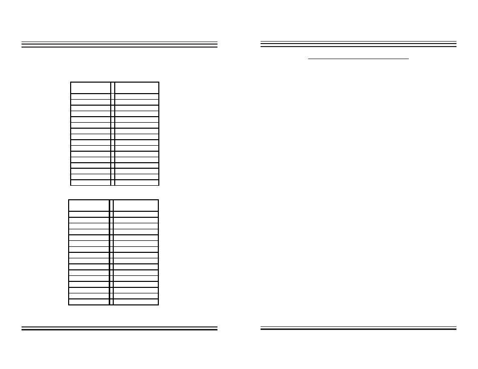
Fig. B: Flow Restrictor Tables
(For 4:1 Concentrate to Product Ratio)
FR-90
ml./min.
gpd
in.
cm.
269
102
1
2.5
233
88
2
5.1
213
81
3
7.6
198
75
4
10.2
183
69
5
12.7
175
67
6
15.2
164
62
7
17.8
154
58
8
20.3
148
56
9
22.9
141
54
10
25.4
136
52
11
27.9
133
50
12
30.5
129
49
13
33.0
128
48
14
35.6
124
47
15
38.1
124
47
16
40.6
PRODUCT RATE
CUT TO LENGTH
FR-180
ml./min.
gpd
in.
cm.
490
186
1
2.5
460
175
2
5.1
430
163
3
7.6
400
152
4
10.2
379
144
5
12.7
356
135
6
15.2
344
131
7
17.8
326
124
8
20.3
311
118
9
22.9
300
114
10
25.4
289
110
11
27.9
281
107
12
30.5
270
103
13
33.0
263
100
14
35.6
259
98
15
38.1
256
97
16
40.6
PRODUCT RATE
CUT TO LENGTH
(GREEN)
(YELLOW or WHITE)
SpectraPure®Inc.
Fax 480.894.6109 Fax us toll-free 1.877.527.7873
E-mail: [email protected] Visit us on the web www.spectrapure.com
15
SpectraPure
®
RO MEMBRANE DIAGNOSTICS
Although RO membranes are capable of maintaining high water quality
over extended periods of time they eventually will begin to deteriorate.
Normally, the conductivity of the permeate water will increase as the
membranes age. By comparing the difference in TDS readings between
the Tap water conductivity and the RO water conductivity, the per-
centage of rejection of the RO membrane may be calculated and the
resultant number may then be used to determine the condition of the
membrane and thus the operator will know when the membrane needs
to be replaced. Membrane failure will be indicated by a reduction of the
percentage of rejection which will be determined by calculating the dif-
ferential between the input and output numbers.
In order to accurately determine the condition of the RO Membrane, a
conductivity tester (TDS meter) capable of reading the tap water
conductivity and the permeate water conductivity has been provided
with this system. With the assistance of the TDS meter you will be able to
easily determine the RO membrane’s condition. (see page 7)
Before performing the diagnostic test on the RO membrane, make sure
that the RO system has been “ON” and producing pure water for a mini-
mum of 10 minutes. Also check the brine (yellow) line to make sure that
water is flowing and that the flow ratio between the permeate water
and the brine water is at a ratio that is > 4 to 1. ( See Page 9). (NOTE: The
pressure gauge should indicate a pressure reading of > 40 PSI during this
15-20 minute test period.
Procedure:
1. Turn on the meter 1 by depressing the on switch.
2. Locate the meter slide switch on the front of the DM-1 TDS meter.
3. Slide the switch to the “Left” and read the Tap water conductivity then
record the reading ________ .
4. Next, slide the switch the to “Right” and read the permeate water
conductivity then record the reading ________.
5. See page 7 on “TESTING THE RO MEMBRANE REJECTION RATE ”