Warnings, Cautions – Superior SDVST-N-B User Manual
Page 14
14
NOTE: DIAGRAMS & ILLUSTRATIONS ARE NOT TO SCALE.
Millivolt Appliance Checkout
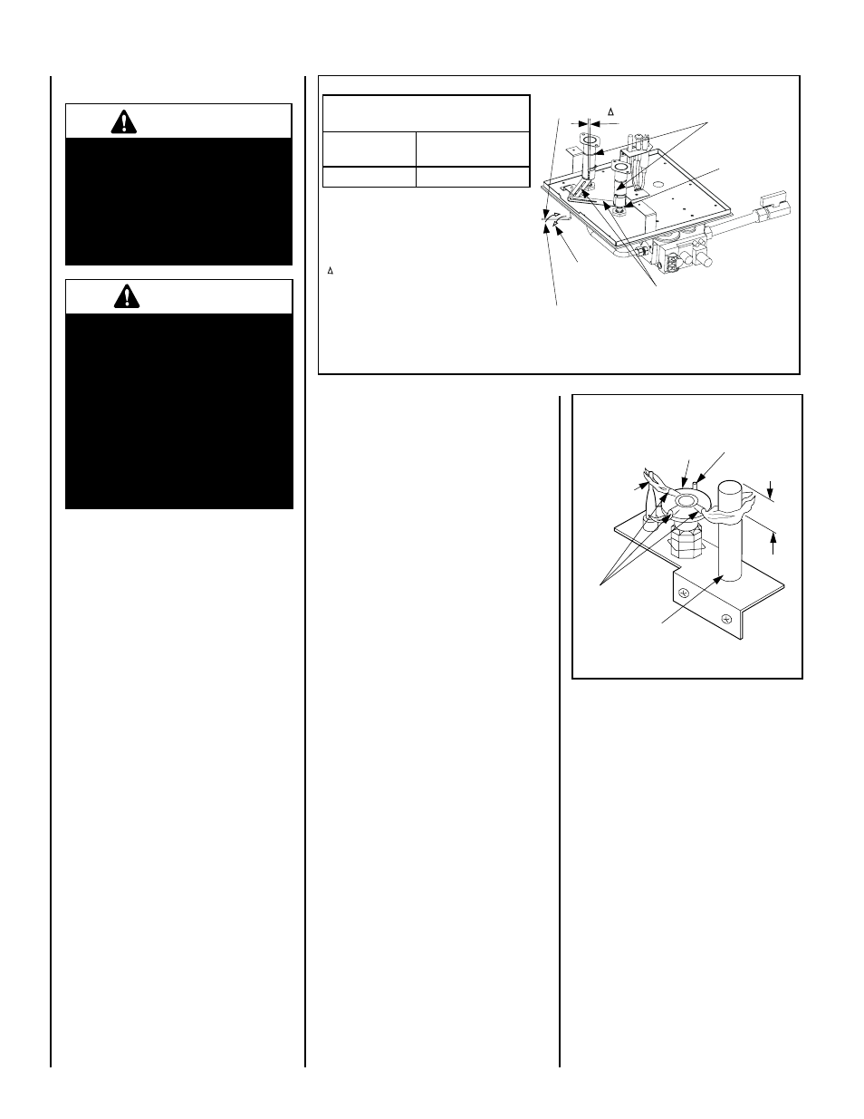
The pilot flame should be steady, not lifting
or floating. Flame should be blue in color with
traces of orange at the outer edge.
The top 3/8" (10 mm) at the pilot generator
(thermopile) and the top 1/8" minimum (tip)
of the quick drop out thermocouple should be
engulfed in the pilot flame. The flame should
project 1" (25 mm) beyond the hood at all three
ports. See Figure 11.
To light the burner, refer to the lighting instruc-
tions on Pages 19 and 20.
1. Locate adjustment rod and adjust air shutter
to the standard setting as shown in Figure
10 (adjustment rod is located in the lower
control area).
Note: Rotating the adjustment rod coun-
terclockwise decreases air and clockwise
increases air.
2. Light appliance (follow lighting procedure
on lighting label in control compartment or
see care and operation manual).
3. Allow the burner to operate for at least 15 min-
utes while observing the flame continuously
to ensure that the proper flame appearance
has been achieved (see Figures 5 and 9 on
Pages 12 and 13). If the following condi-
tions are present, adjust accordingly.
• If flame appears weak or sooty, adjust
the air shutter, incrementally, to a more
open position until the proper flame
appearance is achieved.
• If flame stays lowered blue, adjust the
air shutter, incrementally, to a more
closed position until the proper flame
appearance is achieved.
4. Leave the control knob (off/pilot/on) in the
ON position (and the optional switches, if
installed - wall switch, remote control or
wall thermostat).
5. When satisfied that the burner flame appear-
ance is normal, re-install the lower control
compartment door.
Figure 10
***Main Burner Factory Air Shutter
Opening Setting - All Models
Natural Gas
inches (mm)
Propane Gas
inches (mm)
* TWO 1/8 (3) Slots ** TWO 11/16 (17) Slots
Air Shutter
Adjusting
Rod
Air Shutter
Adjusting
Arms
Orifice
Increase Shutter
Opening In This
Direction
Decrease Shutter
Opening In This
Direction
Air Shutter
Opening
Burner
Venturi
Tube
Note - Both air shutters open and close simultaneously
when the air shutter adjusting rod is moved.
Note - Burners are omitted in this view for clarity.
Adjustment Rod Positions, viewed from above:
* Natural Gas - fully clockwise
** Propane- fully counter clockwise
***Settings are shown for each burner.
Note - Both air shutters open and close
simultaneously when the air shutter adjusting
rod is moved.
Burners are omitted in this view for clarity.
Ref. Air shutter Patent:
U.S. Pat. 5,553,603
Figure 11
Thermocouple
Thermopile
Pilot
Nozzels
MILLIVOLT PILOT ASSEMBLY
3/8" Min.
(9 mm)
Igniter Rod
Hood
Proper Pilot Flame Appearance
WARNINGS
•
Air shutter adjustment should
only be performed by a quali-
fied professional service
technician.
•
Ensure front glass panel are
in place and sealed during
adjustment.
CAUTIONS
•
Soot will be produced if the
air shutter is closed too much.
Any damage due to carboning
resulting from improperly
setting the air shutter is not
covered under the warranty.
•
The air shutter door and nearby
appliance surfaces are hot.
Exercise caution to avoid
injury while adjusting flame
appearance.
Burner Air Shutter Adjustment Procedure