Wiring diagram, Ervice – Southbend P20-FR65 User Manual
Page 26
S
ERVICE
S
ECTIONAL
D
EEP
F
RYER
P
AGE
26 O
PERATOR
’
S
M
ANUAL
1182110
REV
1
SERV
ICE
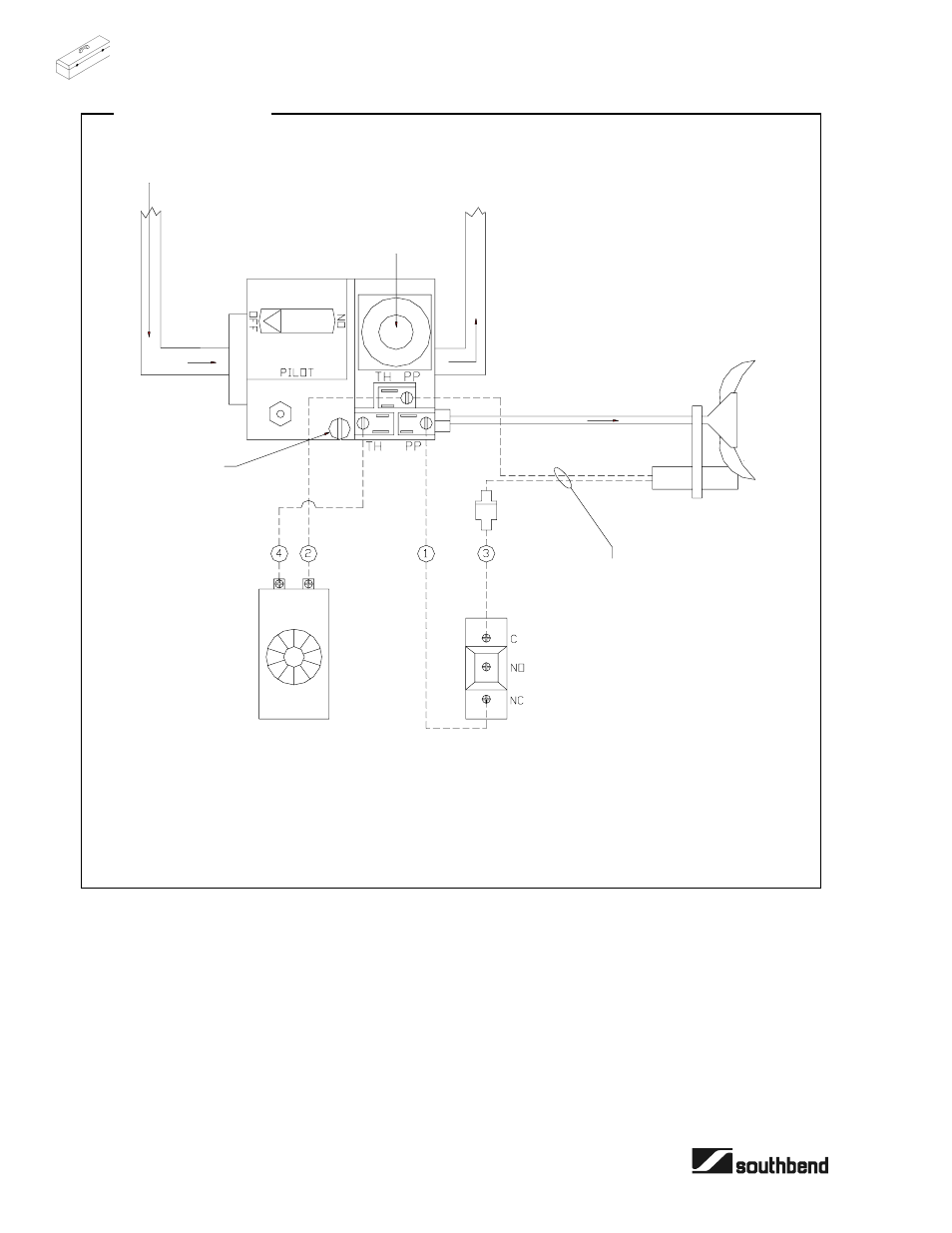
Wiring Diagram
GAS INLET
Notes:
1. High limit switch is set to 450
°F.
2. Voltage measured across TH/PP and TP with main burner on should be greater than 100 mV.
REGULATOR
ADJUSTMENT
MAIN
G
A
S
THERMOPILE
COMPONENT
LEADS
PILOT GAS
PILOT
LIMITING
THERMOSTAT
COMBINATION
GAS VALVE
REGULATING
THERMOSTAT
PILOT
ADJUSTMENT
This manual is related to the following products: