Integrated electric fryer module, Planning information – Sub-Zero IF15/S User Manual
Page 4
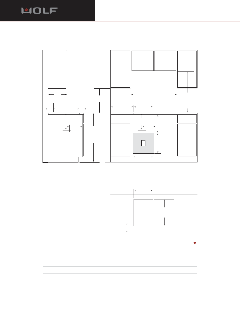
Planning Information
Integrated Electric Fryer Module
M O D E L I F 1 5 / S
Dimensions in parentheses are in
millimeters unless otherwise specified.
4
I N S T A L L A T I O N S P E C I F I C A T I O N S
D I M E N S I O N S
Countertop Cut-Out Width
14" (356)
Recommended Cabinet Width
33" (838)
Countertop Cut-Out Depth
19
1
/
4
" (489)
Minimum Cabinet Depth
22
3
/
4
" (578)
Location of Electrical
Within shaded area
See Installation Instructions shipped with unit for detailed specifications.
7"*
min (178)
CUT-OUT TO
COMBUSTIBLE
MATERIALS
(BOTH SIDES)
14"
(356)
COOKTOP CUT-OUT
WIDTH
14"
(356)
COOKTOP CUT-OUT
WIDTH
33"
(838) RECOMMENDED
CABINET WIDTH
18"
(457)
NOTE: Application shown allows for installation of two 15" (381) modules side-by-side with 33" (838) recommended cabinet width. 18" (457)
recommended cabinet width for installation of single 15" (381) cooktop or module. NOTE: Fryer module must be installed in a base cabinet with
access to manual valve at base of unit to drain oil into heat resistant receptacle. *Minimum clearance from both side edges of cooktop cut-out
to combustible materials up to 18" (457) above countertop. **Minimum clearance from rear edge of cooktop cut-out to combustible materials up
to 18" (457) above countertop.
19
1
/
4
"
(489)
COOKTOP CUT-OUT
DEPTH
2
1
/
2
"
min
(64)
36"
(914)
STANDARD
FLOOR TO
COUNTERTOP
HEIGHT
13"
max
(330)
30"
(762)
COUNTERTOP TO
COMBUSTIBLE
MATERIALS
ABOVE COOKTOP
FRONT OF COUNTERTOP
2
1
/
2
"
min
(64)
19
1
/
4
"
(489)
COOKTOP
CUT-OUT DEPTH
7
5
/
8
"
(194)
12
3
/
8
"
(314)
DRAIN OUTLET
LOCATION
E
13
1
/
2
"
(343)
15"
(381)
15"
(381)
12
3
/
8
"
(314)
6"
(152)
DRAIN OUTLET
LOCATION
2"**
(64)