Sea Frost 372 ROUTE User Manual
Sea Frost Refrigerators
1
372 ROUTE 4 BARRINGTON, NH 03825 USA
TEL (603) 868-5720
FAX (603) 868-1040
1-800-435-6708
E-Mail:[email protected]
www.seafrost.com
SEA FROST BD 12 OR 24 VOLT D.C. SYSTEM
With Water Cooling Option
CONDENSING UNIT LOCATION AND MOUNTING
The water-cooling option should be considered supplemental cooling. Installation
should proceed with a proper air-cooled installation first. The water-cooling feature
should be used to enhance efficiency on occasions when cold-water temperatures are
encountered or interior cabin air temperatures are extreme.
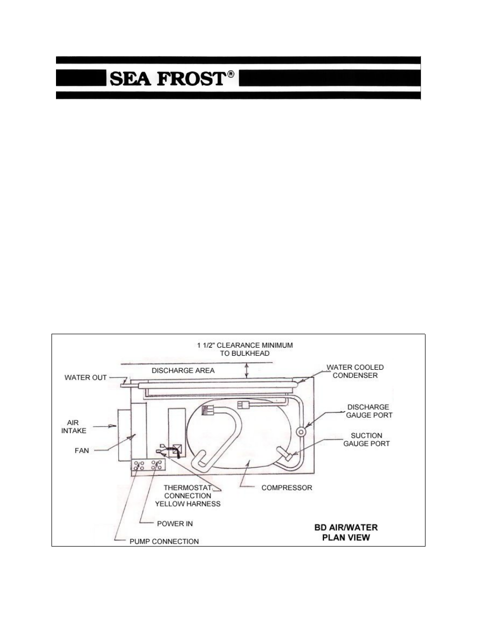
The design of the Sea Frost BD allows placement in an enclosed space such as a cabin
locker or sail locker. Intake air should be drawn in from the cabin area to insure the
coolest, driest air supply. Standard 4" duct hose may be used. Discharge may need to
be vented to allow warm air to escape. Intake ducting from the exterior of the boat may
cause damp salt air to be drawn in which might reduce the life of your BD. This will also
increase below deck moisture. ALLOW 1.5" CLEARANCE BETWEEN THE
CONDENSER (BACK VENT AREA) AND ANY BULKHEAD TO INSURE PROPER
AIRFLOW THROUGH THE CONDENSER.
Document Outline
- CONDENSING UNIT LOCATION AND MOUNTING
- INSTALLATION REQUIREMENTS FOR CONDENSING UNIT
- PUMP INSTALLATION
- INSTALLING REFRIGERANT LINES
- COMPRESSOR CONNECTIONS
- ELECTRICAL CONNECTION
- WIRE SIZE
- CONNECTIONS
- REFRIGERANT CHARGE
- STANDARD THERMOSTAT WIRING CONNECTIONS
- STANDARD THERMOSTAT OPERATION
- OPTIONAL REMOTE THERMOSTAT OPERATION
- OPERATION DESCRIPTION
- DEFROSTING
- OPERATION INSPECTION
- OPERATIONAL INFORMATION
- SERVICE NOTE:
- WATER COOLED MAINTENANCE
- TROUBLESHOOTING
- WIRING DIAGRAM
- WATER PUMP LAYOUT
- Our Repair Policy