Sanyo KHS1822 User Manual
Page 15
10
WM – 700796
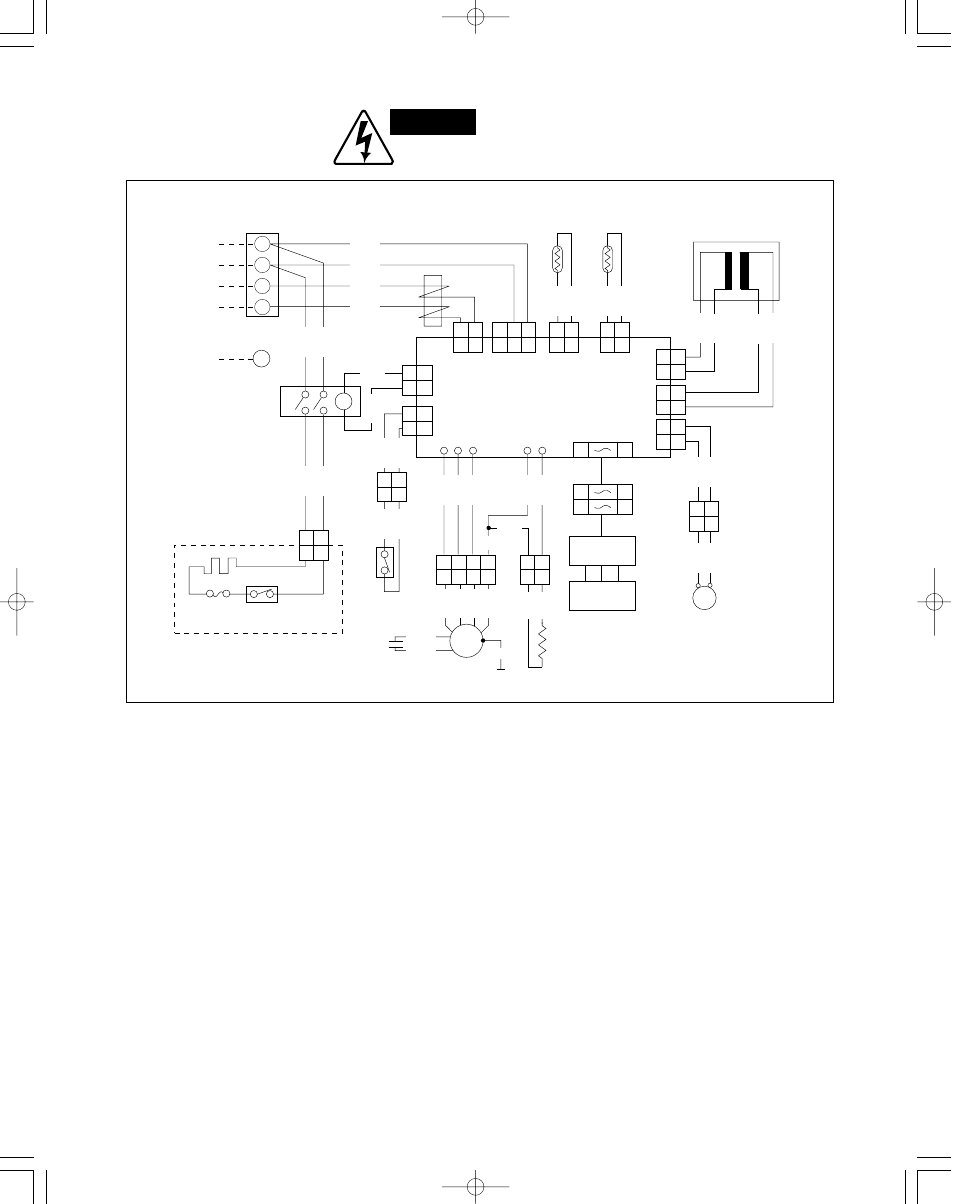
● Electric Wiring Diagram
Indoor Unit: KHS1822
Terminal plate
1
2
3
4
FROM OUTDOOR UNIT
3
3
1
1
3
3
2
2
1
1
1
1
2
2
BLK
BLK
BLK
BLK
1
1
2
2
SG-OUT
3P
SUP
2P
2P
2P
SEC
TH2
TH1
1
2
1
2
1
2
1
2
2P
PRY
1
9
1
9
1
9
Switch
assy
Receiver
assy
Connector
Switch
assy
H M
FM
L LL
YEL
VLT
WHT
2 3
1
4
2 3
1
4
GRY
BRN
PNK
GRY
WHT
VLT
YEL
FM
GRN
G
CONTROLLER
G
Noise
filter
Thermistor
S
P
BRN
BRN
WHT
WHT
2
1
2
1
2P
LM
Transformer
(Coil)
(Room)
Capacitor
ORG
YEL
BLK
WHT
Connector
YEL
YEL
2
1
2
1
2
1
2
1
RED
RED
Resistor
LM
GRY
GRY
Louver
motor
GRY
GRY
Connector
Fan
motor
1
1
2
2
RY
3
4
1
2
5
6
2
2
1
1
2P
HR
2P
H. THERMO
ORG
BLU
Heater
relay
BLK
WHT
1
2
1
2
BLK
BLK
BLK
BLK
Thermostat
BLK
WHT
2
1
2
1
Connector
Thermo
fuse
Thermostat
Heater assy
ORG
WARNING:
To avoid electrical shock hazard, be sure to
disconnect power before checking, servicing
and/or cleaning any electrical parts.
This manual is related to the following products: