Sierra Monitor Corporation D-F7P(W) User Manual
Page 2
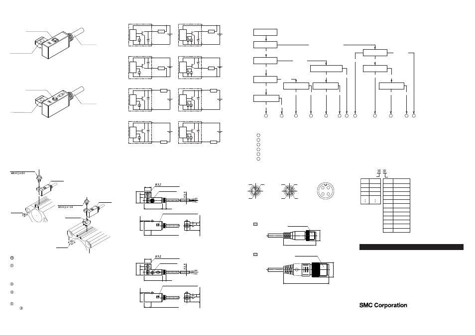
6.How to mount / Mounting bracket
Each actuator has a specified mounting bracket when
mounted to the auto switch. “How to mount/Mount bracket”
depends on actuator type and tube I.D. Please refer to the
actuator catalogue. When an auto switch is mounted for the
first time, please ensure the actuator is of the magnet built-in
type, then prepare brackets that correspond to the actuator.
DC(-)
DC(+)
DC(-)
DC(+)
DC(-)
DC(+)
DC(-)
DC(+)
DC(-)
DC(+)
DC(-)
DC(+)
DC(-)
DC(+)
DC(-)
DC(+)
7.Basic wiring
5.Names and Functions of Individual Parts
8
23
8.5
4.6
4
1
5
7
6
.2
3
.2
1
1
1
Slide the auto switch mounting nut inserted into the mounting rail and
set it at the auto switch mounting position.
Fit the convex part of auto switch mounting arm into the concave part
of auto switch mounting rail. Then slide the switch over the nut.
(CDQ2 series:Fit the convex part of auto switch mounting arm
through the auto switch spacer into the concave part of auto switch
mounting rail.)
Push the auto switch mounting screw lightly into the mounting nut
through the hole of auto switch mounting arm.
After reconfirming detection position, tighten the mounting screw to
secure the auto switch. (Tightening torque of M3 screw should be
0.5 to 0.7N
•
m.)
Modification of the detecting position should be made in the condition
of
.
8.Exterior dimension
D-F79/F7P/J79
D-F79/F7P/J79
D-F79W/F7PW/J79W/F7BA
9.Check flow
When detection failure occurs(stay ON/OFF), please check based
on the next flow.
D-#S-TFI87GB-A
D-F79
D-F79W/F7PW/J79W/F7BAL
8
23
8.5
4.6
4
1
5
7
6
.2
3
.2
1
1
1
2
4
3
1
4
3
1
4
3
2
1
Connector pin assignment
44
1
4
1
0
31.4
D-
PC
A
B
D-
DPC
Exterior dimension of Pre-wired connector
J
K
L
M
2005
2006
2007
2008
O
P
Q
R
S
T
U
V
W
X
Y
Z
A
B
A
C
D
E
B
B
A
A
F
D
A
B
C
D
E
F
---
---
---
---
---
---
D-F79W
D-J79 (Source input mode)
D-J79W/F7BA (Source input mode)
D-J79 (Sink input mode)
D-J79W/F7BA (Sink input mode)
D-F7P
D-F7PW
Indicator lamp
Mounting hole
Lead wire
Indicator lamp
Mounting hole
Lead wire
Switch mounting screw
Switch
mounting
nut
Switch
mounting
nut
Switch mounting screw
Auto switch
Switch spacer
Indicator lamp
Manufacturer’s batch marking
Mounting hole
Most sensitive position
Indicator lamp
Manufacturer’s batch marking
Mounting hole
Most sensitive position
Trouble occurs
2wires / 3wires
Replace the Switch
Load spec.check(1)
Wiring
(output)check
2wires / 3wires
Indicator light
Trouble
condition
Indicator light
Load spec.check(2)
Source voltage
or load voltage
Stay ON(Sometimes OFF)
Stay ON
Stay OFF(sometimes ON)
3wires
Normal
Normal
Abnormal
Normal
Abnormal
Normal
Abnormal
Abnormal
Normal
Stay OFF
Normal
2wires
3wires
Normal
Abnormal
Stay ON
2wires
Switch output parts failure(replace)
Check wiring and correct fault
Replace switch 2 wires --> 3 wires
Switch failure
Replace cylinder. Detectable magnet field in adequate (No magnet)
Replace PLC input board or replace switch 2 wires --> 3 wires
Load spec. check(1) ----- ON voltage > Load voltage-Internal voltage drop
Load spec. check(2) ----- OFF current > Leak current
M8-3pin connector
M8-4pin connector
M12-4pin connector
Connector size M12
Connector size M8
Month
January
February
March
April
May
June
July
August
September
October
November
December
Mark
Mark
Year
Year
Month
Switch
main
circuit
Power
supply
Power
supply
Power
supply
Power
supply
Power
supply
Power
supply
Power
supply
Power
supply
Switch
main
circuit
Switch
main
circuit
Switch
main
circuit
Load
Switch
main
circuit
Switch
main
circuit
Switch
main
circuit
Switch
main
circuit
Switch
main
circuit
Load
Load
Load
Load
Load
Load
Load
Brown
(PinNo.1)
Brown
(PinNo.1)
Brown
(PinNo.1)
Brown
(PinNo.1)
Brown
(PinNo.1)
Brown
(PinNo.1)
Brown
(PinNo.1)
Brown
(PinNo.1)
Blue
(PinNo.3)
Blue
(PinNo.3)
Blue
(PinNo.3)
Blue
(PinNo.3)
Blue
(PinNo.4)
Blue
(PinNo.4)
Blue
(PinNo.4)
Blue
(PinNo.4)
OUT
Black
(PinNo.4)
OUT
Black
(PinNo.4)
OUT
Black
(PinNo.4)
OUT
Black
(PinNo.4)
AUSTRIA
(43) 2262 62280
NETHERLANDS
(31) 20 531 8888
BELGIUM
(32) 3 355 1464
NORWAY
(47) 67 12 90 20
CZECH REP.
(420) 541 424 611
POLAND
(48) 22 211 9600
DENMARK
(45) 7025 2900
PORTUGAL
(351) 21 471 1880
FINLAND
(358) 207 513513
SLOVAKIA
(421) 2 444 56725
FRANCE
(33) 1 6476 1000
SLOVENIA
(386) 73 885 412
GERMANY
(49) 6103 4020
SPAIN
(34) 945 184 100
GREECE
(30) 210 271 7265
SWEDEN
(46) 8 603 1200
HUNGARY
(36) 23 511 390
SWITZERLAND
(41) 52 396 3131
IRELAND
(353) 1 403 9000
UNITED KINGDOM
(44) 1908 563888
ITALY
(39) 02 92711
URL http://www.smcworld.com (Global) http://www.smceu.com (Europe)
Specifications are subject to change without prior notice from the manufacturer.
The descriptions of products in this document may be used by other companies.
© SMC Corporation All Rights Reserved.
Contact