Models, Standard voltage options, Gallons litres draw-off valve – Southbend BELM-30 User Manual
Page 2
1100 Old Honeycutt Road, Fuquay-Varina, NC 27526
(919) 762-1000 www.southbendnc.com
Models:
www.yatesgd.com www.yatesgraphicdesign.com
IntEndEd FOr COMMErCIaL USE OnLY.
nOt FOr HOUSEHOLd USE
.
OPtIOnS and aCCESSOrIES
MISCELLanEOUS
UtILItY InFOrMatIOn
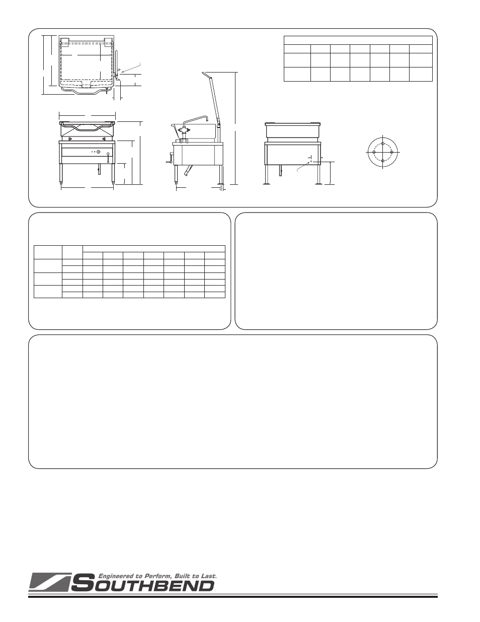
ELECtrICItY: Power requirements are shown below. The skillet
must be grounded.
WatEr: Optional faucets require 3/8" (10mm) outside-diameter tub-
ing connection to base of each faucet.
• Minimum clearance from combustible and noncombustible
construction is 3" (76mm) on sides and 6" (152mm) on rear.
Install on a noncombustible floor. Provide adequate clear-
ances for operation, cleaning, and servicing.
• Check local codes for fire and sanitary regulations.
nOtICE:
Southbend has a policy of continuous product research and improve-
ment. We reserve the right to change specifications and product
design without notice. Such revisions do not entitle the buyer to cor-
responding changes, improvements, additions or replacements for
previously purchased equipment.
Standard voltage options:
208 VAC, 1-phase, 50/60 Hz
208 VAC, 3-phase, 50/60 Hz
240 VAC, 1-phase, 50/60 Hz
240 VAC, 3-phase, 50/60 Hz
Additional-cost voltage options:
220 VAC, 3-phase, 50/60 Hz
380 VAC, 3-phase, 50/60 Hz
415 VAC, 3-phase, 50/60 Hz
480 VAC, 3-phase, 50/60 Hz
220/380 VAC, 1-phase, 50/60 Hz
240/415 VAC, 1-phase, 50/60 Hz
600 VAC, 3-phase, 60 Hz
18 kW power rating (BELM-40 only)
Pantry faucet(s) with swing spout(s)
Single (specify side)
Double
Enclosed support(s) for faucet(s)
Etched volume markings in pan
Gallons
Litres
Draw-off valve
2" (50mm)
3" (76mm)
Vented stainless-steel pan cover
Pan carrier (BELM-40 only)
Steam pan insert
Correctional package
Form BELM Rev 0 (05/07)
BELM-30
BELM-40
l
e
d
o
M
s
e
s
a
h
P
e
n
i
L
r
e
p
s
p
m
A
V
8
0
2
V
0
2
2
V
0
4
2
V
0
8
3
V
5
1
4
V
0
8
4
V
0
0
6
0
3
-
M
L
E
B
)
W
k
2
1
(
1
7
.
7
5
5
.
4
5
0
.
0
5
-
-
-
-
3
3
.
3
3
5
.
1
3
9
.
8
2
2
.
8
1
7
.
6
1
4
.
4
1
5
.
1
1
0
4
-
M
L
E
B
)
W
k
5
1
(
1
1
.
2
7
2
.
8
6
5
.
2
6
-
-
-
-
3
6
.
1
4
4
.
9
3
1
.
6
3
8
.
2
2
9
.
0
2
0
.
8
1
4
.
4
1
0
4
-
M
L
E
B
)
W
k
8
1
(
1
5
.
6
8
8
.
1
8
0
.
5
7
-
-
-
-
3
0
.
0
5
2
.
7
4
3
.
3
4
3
.
7
2
0
.
5
2
7
.
1
2
3
.
7
1
FRONT VIEW
C
D
B
REAR VIEW
SIDE VIEW
TOP VIEW
23-1/2"
(597)
Pan Depth
9-1/8" (232)
28"
(711)
13-1/4"
(337)
40"
(1016)
33"
(838)
A
4" (102)
7-1/2" (191)
1-1/2" (38)
29-3/8" (746)
E
8-3/4" (222)
Water Connection
for Optional Faucet
Electric
Entrance
Four equally spaced 7/16” (11mm)
holes, 3” (76mm) between centers.
REAR FLANGED-FOOT DETAIL
s
t
h
g
i
e
W
g
n
i
p
p
i
h
S
d
n
a
s
n
o
i
s
n
e
m
i
D
c
if
i
c
e
p
S
-l
e
d
o
M
l
e
d
o
M
A
B
C
D
E
t
h
g
i
e
W
0
3
-
M
L
E
B
"
8
/
7
-
8
3
)
7
8
9
(
"
2
/
1
-
3
3
)
1
5
8
(
"
6
3
)
4
1
9
(
"
8
/
5
-
3
3
)
4
5
8
(
"
8
/
3
-
4
7
)
9
8
8
1
(
s
b
l
0
0
6
)
g
k
2
7
2
(
0
4
-
M
L
E
B
"
8
/
3
-
9
3
)
0
0
0
1
(
"
2
/
1
-
3
4
)
5
0
1
1
(
"
8
4
)
9
1
2
1
(
"
8
/
5
-
5
4
)
9
5
1
1
(
"
4
/
3
-
3
7
)
9
9
8
1
(
s
b
l
5
2
7
)
g
k
8
2
3
(
Dimensions shown in inches and (millimeters)