Usb pin-out header – SIIG FREEFLOW 701P48438 User Manual
Page 4
4
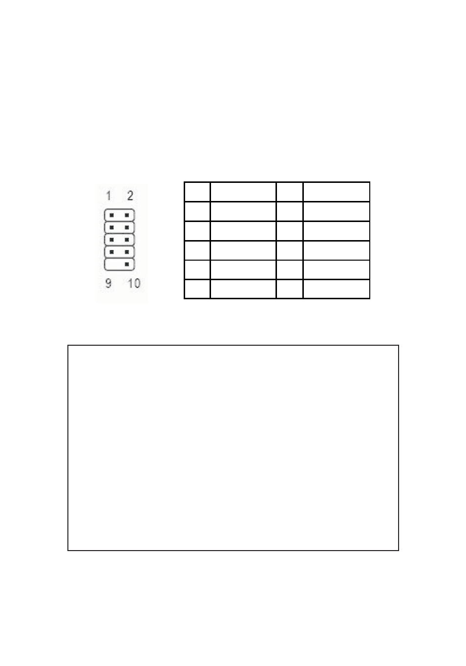
USB Pin-out Header
The internal USB Pin-out Header consists of 9 pins
arranged in 2 rows; the header provides 2 USB ports.
Match up +5VDC (Pin 1) on the 4-Pin USB Connector to
Pin 1 on the pin-out header. Connecting the USB cable
improperly may damage the system. Please refer to your
system's manual for proper connection.
Figure 2. USB Pin-out Header
Note: The diagram and table shows labeling for a
typical motherboard 9-pin pin-out header. Please
note that the 1st pin on the 5-pin row of the FireWire
800+Hi-Speed Combo is labeled pin1 but
corresponds to pin 2 on the diagram, nevertheless ,
the assignment for each pin are identical to the
table. The pin-out header is designed to connect to
front mounted USB ports, flash memory card
readers, or any USB devices that require pin-out
header connection. Reference the image above and
review your computer's manual for proper
connection.
Pin
Assignment
Pin
Assignment
1
+5VDC
2
+5VDC
3
USB- (Data-)
4
USB- (Data-)
5
USB+ (Data+)
6
USB+ (Data+)
7
Ground (GND)
8
Ground (GND)
9
None
10
Ground (GND)