Decode distances, Sdsc 3e – Socket Mobile Secure Digital Scan Card Series 3 User Manual
Page 44
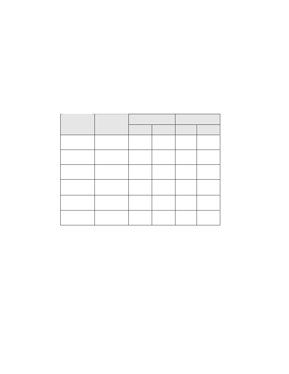
Decode Distances
The following tables list the typical and guaranteed scanning
distances for selected bar code sizes. The minimum element
width (“X Dimension”, “size” or "symbol density") is the width in
mils of the narrowest element (bar or space) in the symbol.
SDSC 3E
Typical
Working Ranges
Guaranteed
Working Ranges
Symbol
Density /Bar
Code Type
/W-N Ratio
Bar Code
Content
/Contrast
Near
Far
Near
Far
6 mil
Code 39; 2.5:1
123
80% MRD
2.25 in
5.72 cm
4.50 in
11.43 cm
3.00 in
7.62 cm
4.00 in
10.16 cm
7.5 mil
Code 39; 2.5:1
ABCDEF
80% MRD
1.75 in
4.45 cm
6.25 in
15.88 cm
2.50 in
6.35 cm
4.75 in
12.07 cm
10 mil
Code 39; 2.5:1
FGH
80% MRD
1.25 in
3.18 cm
7.50 in
19.05 cm
2.00 in
5.08 cm
6.00 in
15.24 cm
13 mil
UPCA; 2.5:1
01234567890
5
80% MRD
2.00 in
5.08 cm
8.50 in
21.59 cm
2.50 in
6.36 cm
7.25 in
18.42 cm
20 mil
Code 39; 2.5:1
123
80% MRD
2.20 in
5.59 cm
12.00 in
30.48 cm
Note 2
10.75 in
27.31 cm
55 mil (
4)
Code 39; 2.5:1
CD
80% MRD
4.30 in
10.92 cm
24.00 in
60.96 cm
Note 2
16.00 in
40.64 cm
Notes:
1.
Contrast measured as Mean Reflective Difference (MRD) at 670 nm.
2.
Near ranges on lower densities depend on the width of the bar code and
the scan angle.
3.
Working range specifications at ambient temperature (23 C).
4.
Retro-reflective label media used for 55 mil bar code.
44 | A
PPENDIX
D:
D
ECODE
Z
ONE