Video/audio signal connections – Sony 1500AP User Manual
Page 93
93
Connections for an A/B Roll Editing System
C
h
apt
er
5
C
o
n
nect
ions and
S
e
tti
n
gs
Video/audio signal connections
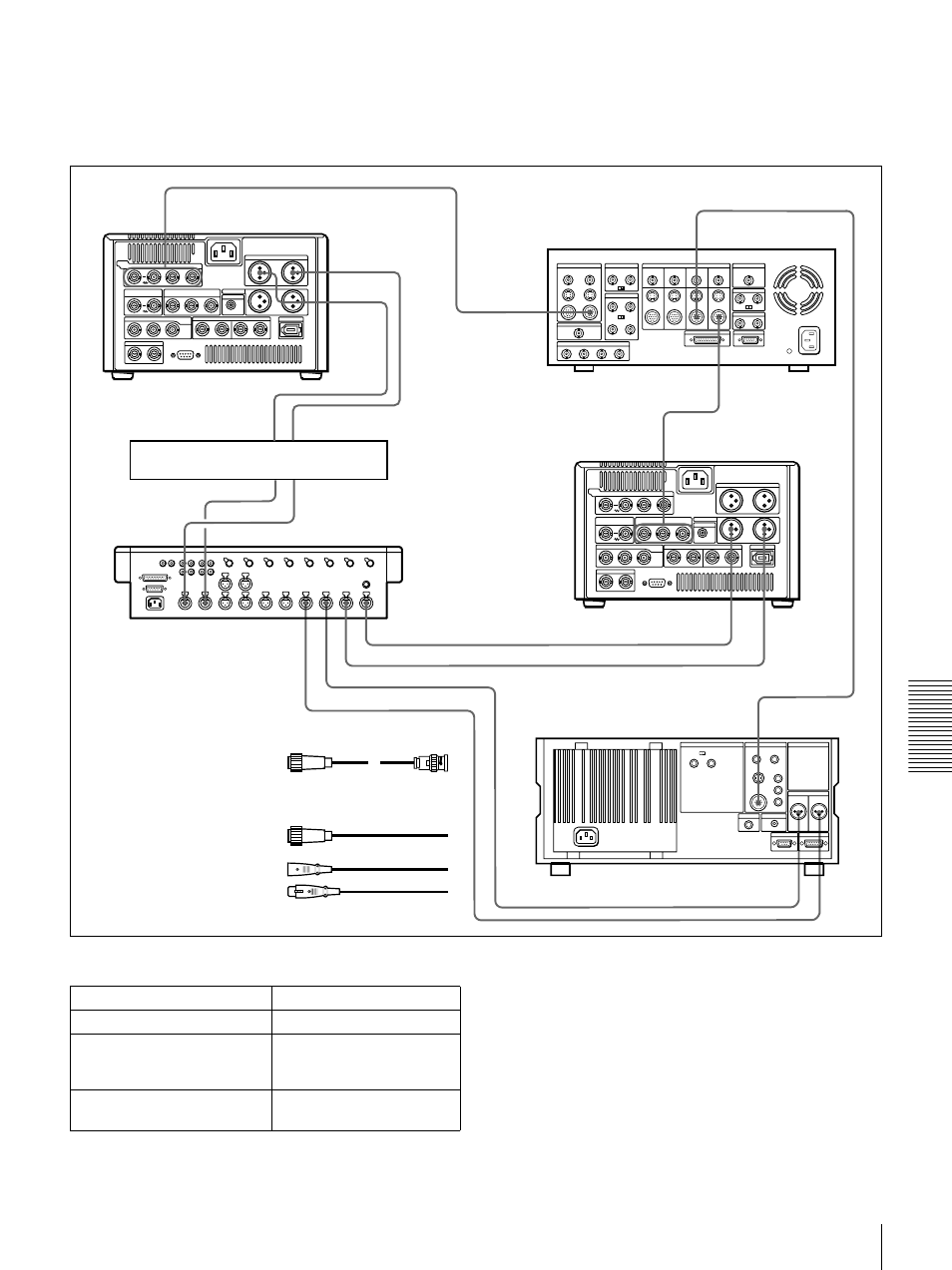
The following shows an example of video/audio signal
connections in an A/B roll editing system.
In this example, analog component signals are used as the
video signals and XLR 3-pin connectors are used as audio
input/output connectors.
Settings on the DSR-1500A/1500AP (recorder)
For details of the video/audio input and audio mode
settings, see “Settings for Recording” on page 32.
VIDEO INPUTS
COMPONENT 2
VIDEO INPUTS
COMPONENT 1
PGM OUT
COMPONENT 1
LINE OUT 2
LINE OUT 1
1
2
3
4
MIC/LINE
IN
COMPONENT 1
OUTPUT
AUDIO OUTPUT
CH-1
CH-2
CH-2 OUT
CH-1 OUT
CH-2 IN
CH-1 IN
1
1
2
3
3
3
3
3
3
VIDEO IN
AUDIO IN
2/4
1/3
AUDIO OUT
1/3
2/4
VIDEO OUT
3
3
DFS-500/500P DME Switcher
C Cable with XLR
connectors (not supplied)
MXP-290
Audio Mixer
DSR-1500A/1500AP
(recorder)
UVW-1600/1600P (player 2)
A 12-pin/3-BNC cross cable
(not supplied; consult your
Sony dealer about this cable.)
DSR-1500A1500AP
(player 1)
DPS-D7 or other delay unit
B 12-pin dubbing cable
(not supplied)
Switch/menu item
Setting
LOCAL/REMOTE switch
LOCAL
CH1 IN LEVEL and CH2 IN
LEVEL menu items
Normally
+4 dBm
REC FORMAT menu item
(see page 65)
DVCAM
(DVCAM indicator lights.)