Replacing the thermocouple, Removing the manifold/burner assembly – State Industries GSX User Manual
Page 21
21
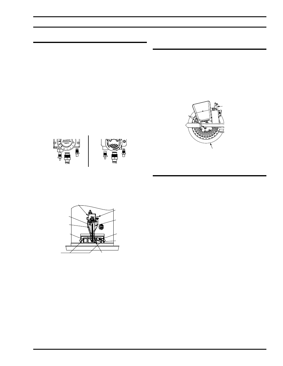
Removing the Burner from the Manifold/
Burner Assembly
Natural Gas (Low Nox) & L.P. Gas Burner
1. Take off the burner by removing the two (2) screws
located underneath the burner.
2. Check the burner to see if it is dirty or clogged. The
burner may be cleaned with soap and hot water.
BURNER
(BOTTOM VIEW)
SCREWS
PILOT ASSEMBLY
(BOTTOM VIEW)
Figure 24
Replacing the Thermocouple
1. Remove the manifold/burner assembly as directed
previously.
2. Lift the retainer clip straight up from the back of
the two piece wire connector (using a flat-blade
screwdriver), then remove the two piece wire
connector from the manifold door.
3. Remove the burner, see Removing the Burner from
the Manifold/Burner Assembly.
4. Pull the thermocouple from the pilot assembly.
IMPORTANT: Be careful not to bend or alter the
position of the pilot assembly components.
5. Insert the thermocouple tip into the holes provided
in the pilot bracket until it clicks into place. NOTE:
The base of the thermocouple must be flush with
the base of the pilot bracket.
6. Position the new thermocouple through the bottom
opening of the two piece wire connector. Be
sure igniter wire is positioned through the middle
opening of the two piece wire connector.
7. Re-attach the burner. Note the orientation of the
burner.
8. See Replacing the Manifold/Burner Assembly.
Removing the Manifold/Burner Assembly
1. Turn off the gas supply to the water heater at the
manual gas shut-off valve. This valve is typically
located beside the water heater. Note the position
of the shut-off valve in the open/on position then
proceed to turn it off.
2. On the lower front of the water heater locate the gas
control valve/thermostat. Before performing any
maintenance, it is important to turn the temperature
dial on the gas control valve/thermostat to its lowest
setting.
3. On top of the gas control valve/thermostat turn the
gas control knob to the “OFF” position. NOTE: On
the White-Rodgers® gas control valve/thermostat
the knob stop must first be depressed before turning
the gas control knob. See Lighting Instructions on
the water heater.
THERMOCOUPLE
MANIFOLD TUBE
PILOT
TUBE
WHITE RODGERS GAS VALVE
ROBERTSHAW GAS VALVE
THERMOCOUPLE
MANIFOLD TUBE
PILOT
TUBE
Figure 22
4. Remove the outer door.
5. Remove the two screws securing the manifold
door assembly to the combustion chamber.
MANIFOLD
SCREWS (2)
TWO PIECE
WIRE CONNECTOR
MANIFOLD
DOOR
TCO
SWITCH
PILOT
TUBE
PIEZO
IGNITER
BUTTON
GAS CONTROL VALVE/
THERMOSTAT
MANIFOLD
TUBE
THERMOCOUPLE
VIEW PORT
Figure 23
6. Disconnect the thermocouple (right-hand thread), pilot
tube, the igniter wire from the igniter button, the two
connectors attached to the TCO switch, and manifold
tube at the gas control valve/thermostat. NOTE: L.P.
Gas systems use reverse (left-hand) threads on the
manifold tube.
7. Grasp the manifold tube and push down slightly to
free the manifold, pilot tube, and thermocouple.
8. Carefully remove the manifold/burner assembly from
the burner compartment. NOTE: Be sure not to
damage internal parts.
REPLACING THE THERMOCOUPLE AND GAS CONTROL VALVE/THERMOSTAT