24 flow diagram – SPX Cooling Technologies ROBINAIR 17700-2K User Manual
Page 26
© 2001 Robinair, SPX Corporation
24
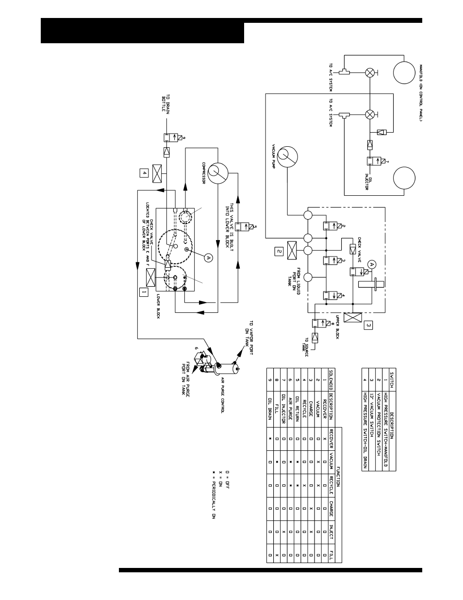
Flow Diagram
INST0576
1.
Low Side Manifold Gauge
2.
High Side Manifold Gauge
3.
Low Side Manifold Valve
4.
High Side Coupler
5.
Oil Injector Check Valve
6.
Vacuum Pump
7.
Expansion Valve
8.
Upper Block
9.
Compressor
10.
Air Purge Control
11.
Lower Block
12.
Return Oil Separator
13.
Accumulator
14.
Filter-Drier
1
2
4
5
6
7
3
8
9
10
11
12
14
13
This manual is related to the following products: