Hardware configuration, Programming, Defaults – Sensory Science 7405 User Manual
Page 3: I/o space, I/o port mapping, Channel mode
Sensoray Model 7405 Instruction Manual — Page 3
Hardware Configuration
The Model 7405 requires the installation of programming
shunts to select various options such as I/O port addresses
and channel operating modes. This section describes these
configuration options.
After configuring the option shunts, the Model 7405 may be
installed in your STDbus backplane and programmed as
explained in the Programming section of this manual.
Both board address and channel output types are established
by installing programming shunts at various locations on the
board. In all of the following discussions of shunt
programming, I denotes an installed programming shunt and
R indicates that no shunt is installed:
Defaults
All option jumpers are set to a standard default configuration
at the factory. If the default configuration is consistent with
your application, you may be able to use the board without
having to reconfigure any jumpers.
I/O Space
Two separate I/O spaces exist on the STDbus: primary and
expanded. Option jumper E8 selects which I/O space the
Model 7405 board will reside in. E8 is factory set to map the
board into primary space.
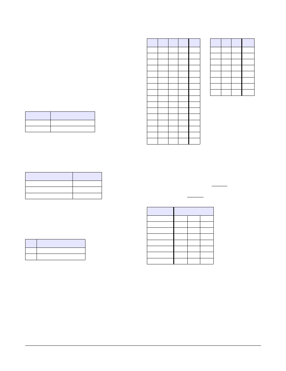
I/O Port Mapping
The Model 7405 occupies two consecutive 8-bit addresses in
the selected STDbus I/O address space. These ports may be
mapped to any even address from 0x00 to 0xFE. Jumpers
are factory installed to locate the board at ports 0xB2 and
0xB3.
The following tables show the jumper configurations for all
possible board addresses. Use the table on the left for the
most significant address nibble, and the table on the right for
the least significant address nibble.
Channel Mode
Each channel has three mode control option jumpers, used to
select either voltage or current output mode. A channel’s
mode control jumpers work as a set. For any given channel,
either all jumpers should be installed or all should be
removed. A jumper set should be installed to configure the
associated channel for current output. Conversely, the
jumper set should be removed to configure the channel for
voltage output.
For example, jumpers A3, B3 and D3 must all be installed to
configure channel 3 for the 4-20mA current output mode.
Jumpers A7, B7 and D7 must all be removed to configure
channel 7 for the ±10 volt output mode.
Programming
Programming of the Model 7405 is accomplished by means
of three STDbus interface registers. One register is used to
let the host processor know when new data may be sent to
the board. The other two registers receive a combination of
channel number and analog channel data from the host.
Symbol
Meaning
I
Shunt installed
R
Shunt removed
Attribute
Default
I/O base address
0xB2
I/O Space
Primary
Analog channel mode
Voltage out
E8
I/O Address Space
I
Primary
R
Expanded
E7
E6
E5
E4
Val
E3
E2
E1
Val
I
I
I
I
0
I
I
I
0
I
I
I
R
1
I
I
R
2
I
I
R
I
2
I
R
I
4
I
I
R
R
3
I
R
R
6
I
R
I
I
4
R
I
I
8
I
R
I
R
5
R
I
R
A
I
R
R
I
6
R
R
I
C
I
R
R
R
7
R
R
R
E
R
I
I
I
8
R
I
I
R
9
R
I
R
I
A
R
I
R
R
B
R
R
I
I
C
R
R
I
R
D
R
R
R
I
E
R
R
R
R
F
Channel
Jumper Set
0
A0
B0
D0
1
A1
B1
D1
2
A2
B2
D2
3
A3
B3
D3
4
A4
B4
D4
5
A5
B5
D5
6
A6
B6
D6
7
A7
B7
D7