Chapter 10 ac specifications, 1 oscillator/clock, Figure 10.1 typical crystal circuit – SMSC USB2513 User Manual
Page 66: Figure 10.2 formula to find the value of c1 and c2, 1 smbus interface, 2 i2c eeprom, 3 usb 2.0, Smbus interface, Usb 2.0, X (c
USB 2.0 Hi-Speed Hub Controller
Datasheet
Revision 1.0 (3-11-09)
66
SMSC USB251x
DATASHEET
Chapter 10 AC Specifications
10.1
Oscillator/Clock
Crystal: Parallel Resonant, Fundamental Mode, 24/48
1
MHz
±350 ppm.
External Clock: 50% Duty cycle
± 10%, 24/48 MHz ± 350 ppm, Jitter < 100 ps rms.
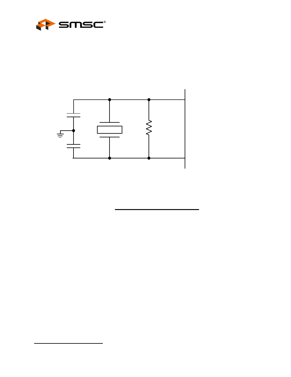
Figure 10.1 Typical Crystal Circuit
Note: C
B
equals total board/trace capacitance.
Figure 10.2 Formula to Find the Value of C
1
and C
2
Figure 10.3 Simplified Form of the Capacitance Formula
10.1.1
SMBus Interface:
The SMSC Hub conforms to all voltage, power, and timing characteristics and specifications as set
forth in the SMBus 1.0 specification for Slave-Only devices (except as noted in
Section 8.3
).
10.1.2
I
2
C EEPROM:
Clock frequency is fixed at 60 KHz
± 20%.
10.1.3
USB 2.0
The SMSC Hub conforms to all voltage, power, and timing characteristics and specifications as set
forth in the USB 2.0 specification. Please refer to the USB 2.0 specification for more information.
1.Only when SEL48 is available and supported.
XTAL1
(C
S1 =
C
B
+ C
XTAL
)
XTAL2
(C
S2 =
C
B
+ C
XTAL
)
C
1
C
2
C
L
1 Meg
Crystal
(C
1
+ C
S1
) x (C
2
+ C
S2
)
(C
1
+ C
S1
+
C
2
+ C
S2
)
C
L
=
C
= (2 x C
L
) - C
s