Parts list, Installation, Specifications – SECO-LARM USA ENFORCER CCD Mini Vandal Color Dome Camera EV-122C-DVC3 User Manual
Page 2: Enforcer ccd mini vandal color dome camera manual
ENFORCER CCD Mini Vandal Color Dome Camera Manual
ENFORCER CCD Mini Vandal Color Dome Camera Manual
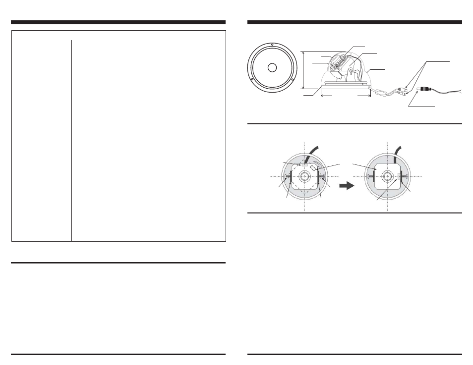
Fig. 1 - Dimensions:
Parts List:
1 x Dome camera
3 x Mounting screws
3 x Drywall anchors
1 x Manual
BEFORE STARTING
1. Please read this manual carefully and keep it for future
reference.
2. Use the camera within given temperature and electricity
limits.
3. Do not aim the LED light directly at the eyes when the
LEDs are on (EV-122C-DVC3 only).
4. Do not point the camera at the sun. Heat could damage
the camera, even when not in use.
5. Do not mount the camera in areas exposed to radiation,
strong magnetic fields, or strong electrical signals.*
Installation:
1. Undo the 2 set screws on the sides of the dome
housing, and remove the dome from the base.
2. Remove the protective film from the inside of the dome
cover.
3. Temporarily connect the camera to a video monitor via
the BNC connector. Connect the camera to a 12VDC
power source.
4. Hold the base of the dome camera with your hand
against the ceiling or wherever you are going to mount
the camera, and try various locations and angles while
watching the video monitor to find the location which
offers the best protection. Mark that location with a pencil.
Note: The ENFORCER dome camera is equipped with
a multi-axis gimbal bracket which will make it applicable
for both walls and ceilings.
5. For wall-mounting applications. Take out the 2 screws
and turn the lens 90
o
clockwise until the wire harness is
adjacent to the mounting bracket. Replace the 2 screws
to secure it. See Fig. 2.
6. Run a hidden, permanent video cable and power supply
6. Do not drop the camera or subject it to strong
vibrations.
* Note: Many video monitors produce strong
electromagnetic fields close to the display CRT,
especially when the monitor is turned on or during
de-Gaussing, which occurs automatically with
many monitors when the monitor is turned on.
Specifications
Important:
Do not cut DC jack. Use SECO-LARM’s
optional EVA-F5521-3Q Pigtail Connector
for easy installation and serviceability.
_________________________________________________________________________________
_________________________________________________________________________________
_________________________________________________________________________________
_________________________________________________________________________________
_________________________________________________________________________________
_________________________________________________________________________________
_________________________________________________________________________________
__________________________________________________________________________________________________________________________________________________________________
_________________________________________________________________________________
_________________________________________________________________________________
_________________________________________________________________________________
_________________________________________________________________________________
_________________________________________________________________________________
_________________________________________________________________________________
_________________________________________________________________________________
_________________________________________________________________________________
_________________________________________________________________________________
_________________________________________________________________________________
_________________________________________________________________________________
_________________________________________________________________________________
_________________________________________________________________________________
_________________________________________________________________________________
_________________________________________________________________________________
_________________________________________________________________________________
_________________________________________________________________________________
_________________________________________________________________________________
*EV-122C-DVC3 only.
cable to the mounting location. To protect the
cables, use conduit.
7. Connect the two cables to the dome camera.
Note: If the video and power cables must be
surface-mounted, run the camera's cables through
the notch in the base.
8. Mount the base to the wall or ceiling at the selected
location with the three mounting screws.
9. Make any necessary adjustments to the horizontal
and vertical angles of the camera itself while
checking the image in the video monitor.
* Viewing angles are approximate.
Important: For the EV-122C-DVC3 (IR version), make
sure the rubber ring around the lens extends out far
enough to make full and flush contact with the dome
cover. This is done to reduce the possibility of night
time image spots.
Replace the dome, taking care not to touch the camera
or scratch the dome.
Test the camera again under the exact lighting
conditions under which it is expected to be used.
10.
11.
12.
Screw
Wire
Harness
Screw
Support
Bracket
Support
Bracket
Support
Bracket
Wire
Harness
Fig. 2 — For wall mounting. Remove the 2 screws and turn the lens 90
o
clockwise
until the wire harness is adjacent to the support bracket, then replace the 2 screws
to secure it.
90
o
Lens
Window
Model No.
Type
Chip
Resolution
Pickup Elements
Scanning System
Sync
Video Output
Lens
Viewing Angle*
Minimum Illumination
Gamma Correction
S/N ratio
Shutter Control
Backlight Compensation
Gain Control
White Balance
Enclosure
Number of IR LEDs
Maximum LED Range
Power Source
Power Consumption
Operating temperature
Dimensions
Weight
Cable Length
Mini IR Vandal Color Dome
1/3" Sony CCD
420 TV Lines
510 x 492 (NTSC/EIA)
2:1 interlace (V:59.94Hz, H:15.734KHz)
Internal
1V p-p, Composite @ 75 Ohms
3.6mm / F2.0
92
o
0.4 Lux (LED off) 0.0 Lux (LED on)
0.45
>48dB
Auto 1/60 ~ 1/100000
Auto & Manual
Auto
Automatic
IP66 Weatherproof
21
Up to 50' (15m)
12 VDC ±10%
350mA
14
o
~122
o
F (-10
o
~50
o
C)
4
1
/
4
" X 3" (108 X 76 mm)
0.9 lb. (405g)
24" (61 cm)
Mini Vandal Color Dome
1/3" Sony CCD
420 TV Lines
510 x 492 (NTSC/EIA)
2:1 interlace (V:59.94Hz, H:15.734KHz)
Internal
1V p-p, Composite @ 75 Ohms
3.6mm / F2.0
92
o
0.4 Lux
0.45
>48dB
Auto 1/60 ~ 1/100000
Auto & Manual
Auto
Automatic
IP66 Weatherproof
N/A
N/A
12 VDC ±10%
120mA
14
o
~122
o
F (-10
o
~50
o
C)
4
1
/
4
" X 3" (108 X 76 mm)
0.8 lb. (365g)
24" (61 cm)
EV-122C-VWA3
EV-122C-DVC3
LEDs*
BNC(F)
Connector
Support
Bracket
Base
DC Jack
3" (76mm)
Lens
4
1
/
4
"(108mm)
SIDE VIEW
Important:
Do not cut DC Jack
or Video Jack as
warranty will
be voided.
Dome
Housing