Mounting/installation (continued ), Layout of the input block, Position of end plate – Sierra Monitor Corporation EX250-SEN1 User Manual
Page 6
8
9
Mounting/Installation (continued )
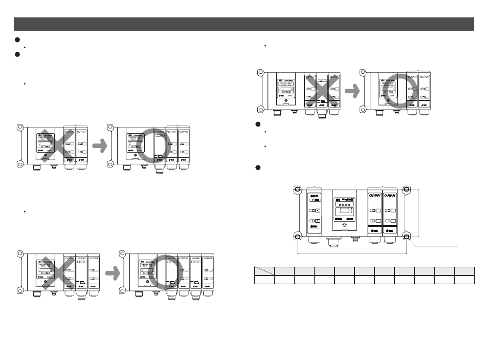
Layout of the Input Block
Position the Input Block on the left side of the SI Unit.
Layout of the EX9 series Output Block / Power Block
Position the Output Block / Power Block on the right side of the SI Unit and between
the SI Unit and solenoid valve or End Plate R (on the Output Block side).
1) Output Block for high wattage load
The Output Block for high wattage load cannot be used independently.
Be sure to combine with the Power Block for use.
2) Position of Output Block for high wattage load
The Output Block for high wattage load cannot be mounted at the place nearer to
the SI Unit than the Power Block. However, that place is acceptable if the Power
Block is located between SI Unit and the Output Block for high wattage load.
3) Output Block for low wattage load
The Output Block for low wattage load cannot be mounted at the right side of the
Power Block. Mount to the place nearer to the SI Unit than the Power Block.
Position of End Plate
Be sure to connect the End Plate (on the Input Block side) at the left end of the
manifold.
When the valve is not connected, be sure to connect the End Plate R (on the
Output Block side) at the right end of the manifold.
Installation example Dimensions with solenoid valves unconnected [Unit: mm]
1
2
3
4
5
6
7
8
9
10
L
114
135
156
177
198
219
240
261
282
303
L
m
[mm]
* Each dimension shows the unit without solenoid valves connected and with an End Plate
R (on the Output Block side) connected. Standard settings of L dimensions are with 10
or less m blocks. Ask SMC sales for the setting with over 10 blocks mounted.
Refer to the individual specifications for the dimensions when the solenoid valves are
connected.
Wiring (power supply, communication, input/output) and piping are all in one direction.
Space for wiring and piping is required in that direction.
SI Unit
For high
wattage load
EX9-OEP1
SI Unit
Power
Block
EX9-PE1
For high
wattage load
EX9-OEP1
SI Unit
For high
wattage load
EX9-OEP1
For high
wattage load
EX9-OEP1
For high
wattage load
EX9-OEP1
Power
Block
EX9-PE1
Power
Block
EX9-PE1
For high
wattage load
EX9-OEP1
Power
Block
EX9-PE1
SI Unit
SI Unit
SI Unit
For low
wattage load
EX9-OET1
For low
wattage load
EX9-OET1
Power
Block
EX9-PE1
For low wattage load
EX9-OET1
0
0
1
1
EX250
EX250
SOL
SOL
NS
NS
PWR
PWR
SETTINGS
SETTINGS
1
1
0
0
MS
MS
0
0
1
1
0
0
1
1
66
L = 21 x m + 93
* The number of Input Blocks + The number of Output Blocks + The number of Power Blocks : m
The number of
Input Blocks
The number of
Output Blocks
Mounting hole for 4-M4
Thickness : 13.2