Sanus Systems Motorized Mount LA112 User Manual
Page 13
6901-100189 <01>
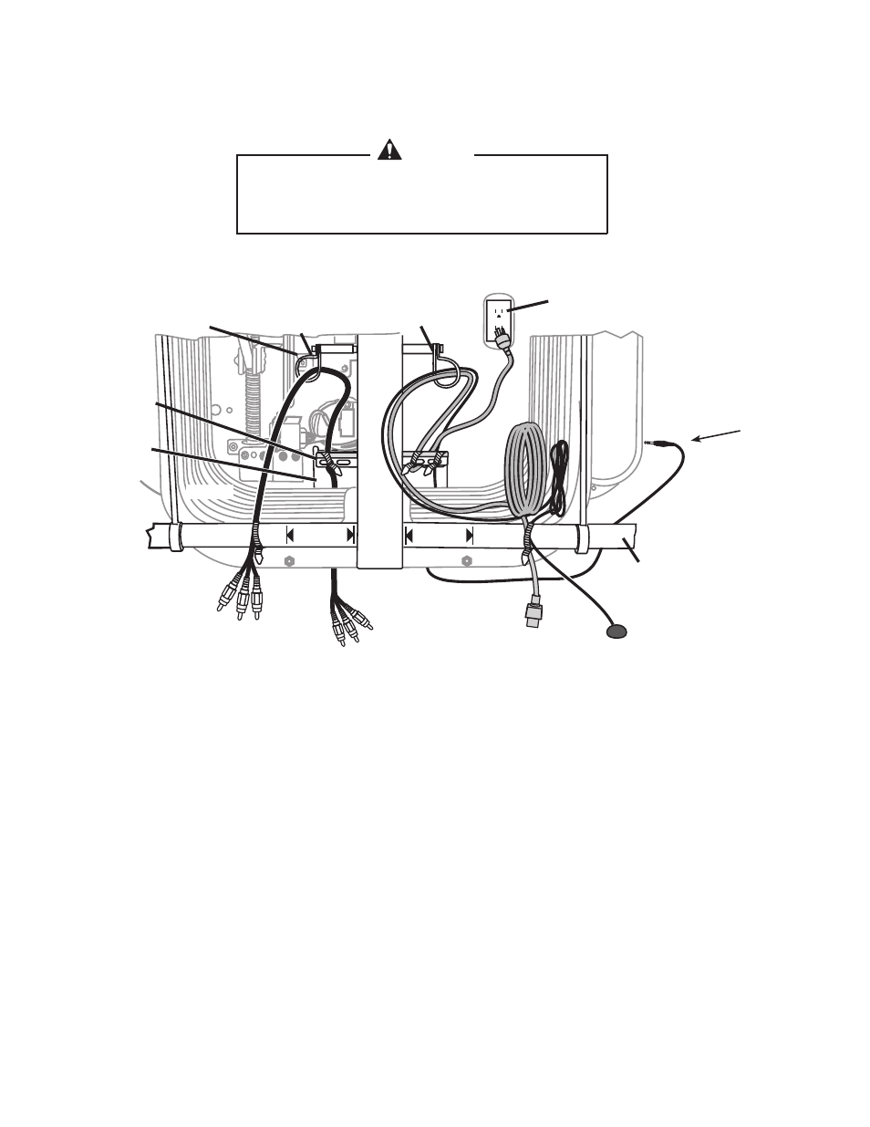
For Power Outlets Located Inside the Bellows
[06]
[08]
Route the AV cables over the bottom cross bar, through the left cable loop [a], then through the cable
access port at the bottom of the arm assembly.
Route the power cord [08] over the bottom cross bar, through the opposite cable loop [B], then through the
cable access port at the bottom of the arm assembly. Disconnect the plug end of the IR receiver cable [06]
and route the cable over the bottom cross bar, through the right cable loop [B], then through the access
port at the back of the arm assembly.
Secure the cables to the bottom cross bar with cable ties [26] as shown. Be sure to keep all cables at least
5cm (2 in.) away from the center beam!
Check that the cables are long enough to allow free movement of the arm assembly, but are not long
enough to get caught in the mechanical parts of the arm assembly. Using the remote, adjust the arm up,
down, and side to side through its full extension. Secure the cables to the cable bar [C] at the back of the
arm assembly.
Avoid potential property damage! Keep all cables away
from the center beam of the arm assembly. Do not place
cables closer than 5cm (2 in.) on either side of the beam.
CauTION
[B]
[a]
[C]
AV Cables
to TV
AV Cables from
Component
TV Power
Cord
AV Cable Loop
Bellows
No Cable
2” (5 cm)
No Cable
2” (5 cm)
Cable Bar
Cable Hole
Bottom Cross Bar
IR Receiver Eye
TV Power outlet
inside belows.
Cable Tie Anchor
TV Power &
IR Receiver Hook