Operation and controls – SRS Labs SR560 User Manual
Page 14
OPERATION AND CONTROLS
10
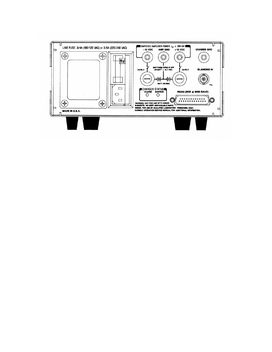
Figure 3: SR560 Rear Panel
REAR PANEL OPERATING SUMMARY
The SR560 rear panel is pictured in Figure
3. Various interface and power connectors
are provided, along with fuses and charger
status LEDs.
AC Power Input
The power entry module contains the
receptacle for the AC line cord and fuse.
The line fuse should be a 1 A slow-blow for
100/120 VAC operation, or a 1/2 A slow-
blow for 220/240 VAC operation.
Amplifier Power Output
The -12 V, +12 V, and AMP GROUND
banana jacks provide external DC power up
to 200 mA for use as a bias source
referenced to the amplifier's floating power
supplies.
The CHASSIS GROUND banana jack is
provided to allow the amplifier's ground to
be referenced to the chassis. If the unit is
connected to an AC power source via a
three prong grounding plug, the chassis
ground is connected to the AC line ground
conductor.
Battery Charger
The two 3 A slow-blow fuses protect the
battery supply and charging circuitry. If
these fuses are blown, battery power will be
unavailable, and charging of the batteries
will not be possible.
When both the positive and negative supply
batteries are dead, the red "CHARGE" LED
will be on brightly, and the batteries will be
charging at a fast rate. When the batteries
approach a fully charged condition, the
charging current will be reduced to complete
the charge and maintain the batteries.
Because the batteries charge at different
rates, the indicators on the rear panel can
reflect the charge status of the positive and
negative batteries independently. When
one set of batteries switches to the
"MAINTAIN" mode, the red "CHARGE" LED
will be reduced to half brightness, and the
yellow "MAINTAIN" LED will turn on at half
brightness. When both batteries switch to
"MAINTAIN", the red "CHARGE" LED will