Stanton SA-12 User Manual
Sa-12, Warranty rotating and replacing the os2, Owner’s manual
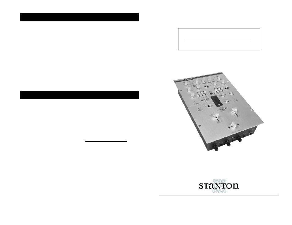
SA-12
D J C R A Z E S I G N A T U R E M I X E R
STANTON MAGNETICS, INC
[email protected] • (954) 689-8833
w w w . s t a n t o n m a g n e t i c s . c o m
OWNER’S MANUAL
© 2001, Stanton Magnetics, LLC
This unit has been designed and man -
ufactured using quality components.
Therefore, it is warranted to be free
from defects in materials (limited as
specified below), and workmanship for
a period of twelve (12) months from the
original purchase date. During this
period, all service and parts necessary
to repair a defect will be free of charge.
This limited warranty applies to
mechanical parts which are subject to
wear and tear as specified: Faders,
specified durability: 15,000 cycles;
Rotary potentiometers, specified dura -
bility: 10,000 cycles; Switches, speci -
fied durability: 10,000 cycles.
Consequently, the parts listed above
are warranted to be free from defects in
materials and workmanship for a peri-
od of thirty days (30) days from the
original purchase date.
For the warranty to be valid, please
complete the warranty registration card
attached or fill out the online registra -
tion
at www.stantonmagnetics.com
Mail completed warranty cards to:
Stanton Magnetics, Inc, 3000 SW 42st
• Hollywood, FL 33312
WARRANTY
ROTATING AND REPLACING THE OS2
ROTATING INSTRUCTIONS
1 . Remove the face plate.
2. Remove the 2 outer screws from the
round OS2 plate (removing the 2 inner
screws will detach the fader from the
plate)
3. Rotate the plate to the desired posi -
tion and tighten the screws back into
the top and bottom holes.
REPLACING INSTRUCTIONS
1. Remove the the face plate.
2. Remove the 2 outer screws from the
round plate (removing the 2 inner
screws will detach the fader from the
plate)
3. Remove the OS2 assembly and dis -
connect the cable coming from the
mixer.
4. Set the replacement fader assembly
in the desired position and place the
screws back in the top and bottom
holes.