Connections, Ex500 connections, Caster installation – Samson EX500 User Manual
Page 14: Ex500 xlr wiring diagram caster installation, Xlr balanced wiring guide
12
Connections
1
3
2
2
3
1
Hot
Cold
Female XLR
Male XLR
Hot (2)
Cold (3)
Common (1)
Common
Hot
Cold
Hot (2)
Cold (3)
Common (1)
Common
Solder Points
End View
End View
Solder Points
1
2
3
2
1
3
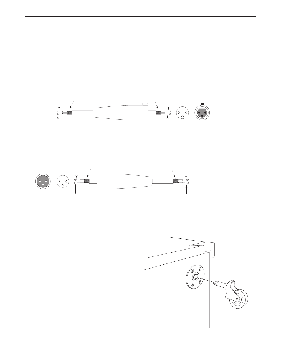
XLR Balanced Wiring Guide
The EX500’s input and outputs utilize industry standard XLR connectors. Below is a detailed wiring diagram for
the EX500 XLR connectors.
EX500 XLR WIRING DIAGRAM
CASTER INSTALLATION
•
Locate the four casters in the EX500
shipping carton.
•
Now locate the four caster recepta-
cles which you’ll find in the four cor-
ners on the back of the unit.
•
Insert the caster into the receptacle
until you feel the caster snap into
place.
•
Turn the EX500 on its back for easy
transport.
See also other documents in the category Samson Microphones:
- MediaOne 5a (72 pages)
- Q3 (9 pages)
- Expedition EX20 (17 pages)
- Bass Enclosure VX410 (4 pages)
- Resolv 65a RESOLV65A (52 pages)
- Resolv A8 (16 pages)
- S12 (2 pages)
- CL5 (10 pages)
- SE50 (8 pages)
- D1500 (2 pages)
- S40 (11 pages)
- dB1500a (64 pages)
- SUB88 (68 pages)
- VR88 (16 pages)
- Qmic Hypercardioid (2 pages)
- Cardioid Q2 (2 pages)
- Airline 77 (2 pages)
- R11 (2 pages)
- 215XL (4 pages)
- Sub120 (18 pages)
- G Track (88 pages)
- G-Track USB Series (2 pages)
- Stage Series PXD1 Beltpack Transmitter (No Microphone, No Receiver) (12 pages)
- S-MAX MD2 Pro 2-Channel Passive Direct Box (32 pages)
- Concert 99 Presentation Frequency-Agile UHF Wireless System (D: 542-566 MHz) (84 pages)
- Concert 288 Presentation Dual-Channel Wireless Microphone System with 2 Headset Mics & 2 Lav Mics (H: 470 to 518 MHz) (104 pages)
- S-MAX MD1 Single Channel Passive Direct Box (32 pages)
- S-MAX MCD2 Pro 2-Channel Passive PC Direct Box (36 pages)
- S-MAX MDA1 Single-Channel Active Direct Box (32 pages)
- Q7x Dynamic Supercardioid Handheld Microphone (44 pages)
- CM12C Hanging Choir Microphone (Black) (2 pages)
- S-MAX MD1 Pro Single Channel Passive Direct Box (36 pages)
- AirLine Micro Wireless Earset System (K6: 480.475 MHz) (20 pages)
- HT6 Wireless Handheld Microphone Transmitter (Channel 11) (64 pages)
- AirLine 88x Wireless Guitar System (K: 470 to 494 MHz) (20 pages)
- AH7 Transmitter with QE Fitness Headset Microphone (K3: 492.425 MHz) (12 pages)
- AH7 Transmitter with QE Fitness Headset Microphone (K5: 479.100 MHz) (52 pages)
- HT6 Professional Handheld Microphone Transmitter (Channel 3) (64 pages)
- AirLine 99m AH9 Wireless UHF Fitness Headset System (K: 470 to 494 MHz) (72 pages)
- C01 Condenser Microphone (8 pages)
- C01 Condenser Microphone (8 pages)
- LM10x Omnidirectional Lavalier Microphone (8 pages)
- AirLine 88x Wireless Fitness Headset Microphone System (D: 542 to 566 MHz) (84 pages)
- SE10x Omnidirectional Earset Microphone for Wireless Transmitters (Beige) (8 pages)