Appendix adjustment of bi-direction position – Seiko Instruments V-64S User Manual
Page 24
Appendix Adjustment of bi-direction position
Appendix Adjustment of bi-direction position
1.
2.
3.
4.
5.
6.
7.
8.
9.
10.
11.
12.
Adjust the bi-direction position of each head. Reading the result of [BIDIRECTION1],
[BIDIRECTION2] and [BIDIRECTION3] print, enter the value.
* When adjusting [NORMAL2] print mode, select [BIDIRECTION2]
and adjusting [FINE DRAFT] print mode, select [BIDIRECTION3].
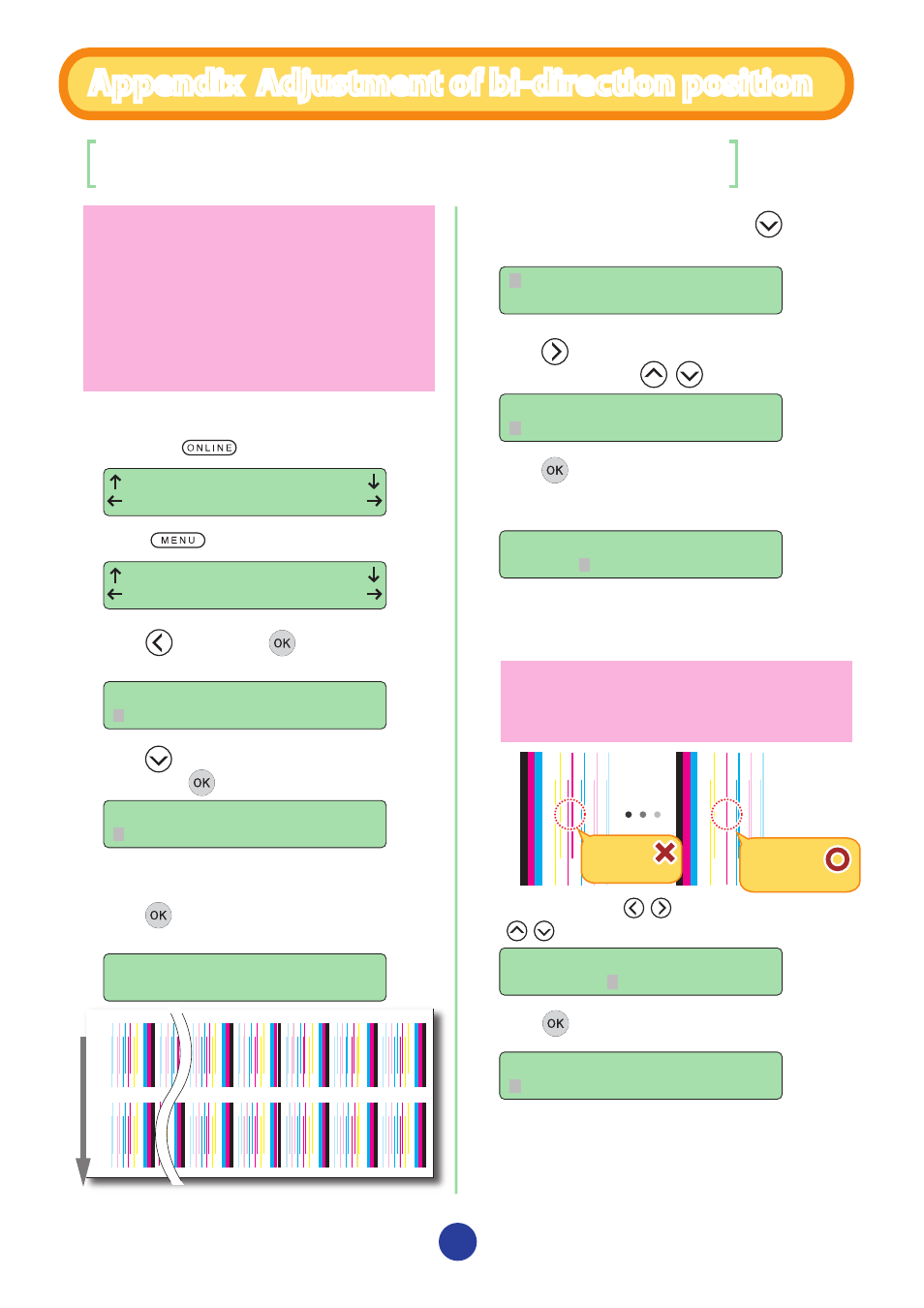
Enter the number of the pattern where two lines are
aligned most closely. For example, when setting the M
color Print head, in “-21” in the figure to the right, two lines
are separated and in “-8” two lines are aligned in one. So
“-8” is the correct value.
This Printer has preset bi-direction position adjustment values for
major media. Basically, the adjustment is not required. But, if you
notice the followings in the bi-directional print ([BIDIR]) shown in
page 21 of this Guide, print the bi-directional adjustment pattern
and set each of the Print head position correctly.
- bleeding (in a single color or different colors)
- bleeding of sharp lines such as register marks (in a single color
or different colors)
- uneveness of mixed colors
* Transfer of the preset values are effective only when new media are registered by
Windows or when the existing media information is copied by panel operation.
Select the digit with , keys and change the value with
, keys.
INK
MEDIA REG
MEDIA
M.ADV
-21
-8
-32
-31
-30
-29
-28
-28
-32
0
+1
+2
+3
+4
+31
media adv
anc
e dir
ec
tion
PRINTER
SETUP
ADJUST
HEATER
#TEST PRINT
NOZZLE PRINT
#BIDIR ADJ1 L XXXXXX
#Y >+00
#BIDIR ADJ1 L XXXXXX
#M >+00
#BIDIR ADJ1 L XXXXXX
#M *+00
#BIDIR ADJ1 L XXXXXX
#M >-08
#BIDIR ADJ1 L XXXXXX
#M >-08
#TEST PRINT
BIDIREC TION1
#TEST PRINT
EXECUTING
NG
OK