Display panel, Rear view – JVC HR-E539EE User Manual
Page 31
EN
31
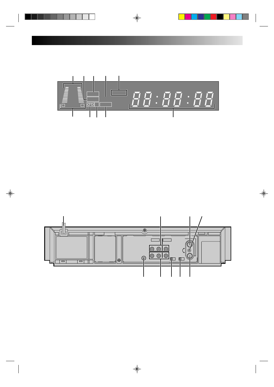
DISPLAY PANEL
R E C
TIMER
PLAY
NTSC
M
SP LP
+8
4
0
6
10
–20dB
NORM
L
R
9
0
7
6
3
4
5
2
1
8
1 B.E.S.T. Picture System Display* (
੬
pg. 18)
Audio Level Indicator*
2 PLAY Indicator (
੬
pg. 10)
3 REC[ORD] Indicator (
੬
pg. 16)
4 NTSC Indicator (
੬
pg. 24)
5 Tape Speed Indicator (
੬
pg. 16)
* Available with HR-E639EE only.
6 Audio Mode Indicator* (
੬
pg. 15)
7 "Cassette Loaded" Mark
8 Counter Memory Indicator (
੬
pg. 13)
9 "TIMER" Indicator (
੬
pg. 21)
0 Clock/Counter/Channel Display (
੬
pg. 6)
1 Mains Power Cord (
੬
pg. 3)
2 AUDIO and VIDEO IN Connectors (
੬
pg. 22)
* The HR-E539EE has only one Audio input connector.
3 ANT. IN Connector (
੬
pg. 3)
4 RF Output Channel Adjustment Screw (
੬
pg. 4)
5 Remote PAUSE Connector (
੬
pg. 23)
6 AUDIO and VIDEO OUT Connectors (
੬
pg. 3)
* The HR-E539EE has only one Audio output connector.
7 TEST Switch (
੬
pg. 4)
8 SYSTEM Swich (
੬
pg. 4)
9 RF OUT Connector (
੬
pg. 3)
REAR VIEW
ANT. IN
RF OUT
32
40
PAUSE
TEST
OFF – ON
OUT
AUDIO
VIDEO
IN
OUT
IN
R
L
SYSTEM
K – G
1
4
3
7 8 9
2
6
5