Johnson Controls TG9S*MP User Manual
Page 17
364861-UIM-B-0708
Johnson Controls Unitary Products
17
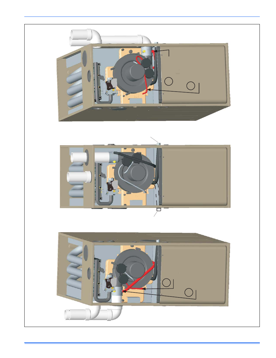
FIGURE 23: Upflow Configuration
INDUCER
ROT
A
TED
FOR
LEFT
SIDE
VENTING
(As
required
for
130K
model)
UPFLOW
AS
RECEIVED
(Except
for
130K
Model)
INDUCER
ROT
A
TED
FOR
RIGHT
SIDE
VENTING
When
drain
hose
routing
changes
are
required,
be
sure
to
cap
all
un-used
openings.
If
rerouting
hoses
-
excess
length
should
be
cut
of
f
so
that
no
sagging
loop
s
will
collect
and
hold
condensate,
which
will
cause
the
furnace
to
not
operate.
Shorten
pressure
switch
hose
Re-route
and
shorten
pressure
switch
hose
Shorten
rain
gutter
hose
Move
rain
gutter
hose
to
this
position
For100,
120&
130Kinput
furnaces,the
condensate
drainis
plumbedtoward
thelef
tcasing
outletfrom
thefactory
.
For 040, 060 & 080K input furnaces, the condensate
drain is plumbed toward the right casing outlet from the factory.
Condensate
drain
may
exit
cabinet
on
either
side.
1
2
1
2
130
K
Model
does
not
have
provisions
for
top
venting,
it
must
be
vented
through
a
side
opening.