Operation, Specifications – Jensen ANHD20 User Manual
Page 5
5
OPERATION
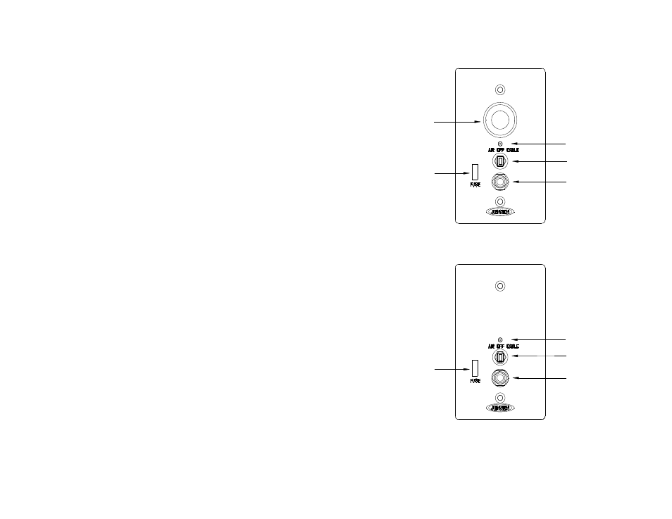
1. Select the desired source by moving the switch located on the front of the wall plate. Select either
“AIR” or “CABLE”. AIR will activate the roof mounted antenna which will provide over-the-air
TV and AM/FM reception. Selecting CABLE will enable you to receive signals from your external
Cable Service provider and AM/FM reception. Selecting “OFF” will disable the system completely
and is recommending when the vehicle is not in use or storage. Note the Red LED indicator will be
On in the “AIR” & “CABLE” positions. See Figures 8 & 9.
2. Next turn on all TV’s and access your on screen menu. (refer to your TV owner’s manual). If you
selected “AIR” ensure that TV tuner is set to receive over-the-air ATSC/NTSC signals. Activate the
TV’s auto programming sequence to scan / store available channels.
3. If you selected “CABLE”, then set your TV tuner to cable and activate the TV’s auto programming
sequence to scan / store available channels.
4. The 7.5 Amp DC Receptacle is designed to power DC TV’s or other small amperage DC devices.
The 7.5A fuse located on the front of the wall plate protects this receptacle and the power to the roof
antenna. If this fuse blows then the antenna will not work. Do not connect high current devices.
5. Other wall plates do not have the DC receptacle and are fused at 1 Amp to protect the electronics.
*
Warning: Replace Fuse with the same Fuse type & current
rating. Failure to do so may cause damage and void warranty.
SPECIFICATIONS
POWER SUPPLY……………………………………………….9 – 16 VDC negative ground at 85mA
IMPEDANCE…………………………………………………………………………………….....75Ω
FREQUENCY RANGE………………………..40 – 850MHz, 500 – 1700KHz (AM, FM, VHF, UHF)
E-PLANE DIRECTIVITY…………………………………………………………....Omni-Directional
GAIN…………………………………………………………………………………..….15dB (typical)
GAIN FLATNESS………………………………………………………………….……0.5dB (typical)
OIP3………………………………………………………………………………..…80dBmV (typical)
OPERATING TEMPERATURE…………………………………………….-40C ~ 85C (-40F~ 185F)
OVERALL DIMENSIONS……………………………………………….8”(H) x 12.75”(W) x 14”(D)
Specifications subject to change without notice.
This device complies with Part 15 of the FCC Rules. Operation is subject to the following 2 conditions:
(1) This device may not cause harmful interference.
(2) This device must accept any interference received, including interference that may cause undesired
operation.
NOTE: The manufacturer is not responsible for any radio or TV interference caused by unauthorized
modifications to this equipment. Such modifications could void the user’s authority to operate this
equipment.
ANWP12V
ANWP
FIGURE 8
FIGURE 9
7.5 AMP MINI
ATM FUSE
7.5 AMP MAX
DC RECEPTACLE
TV1 OUTPUT
CONNECT TO TV
1 AMP MINI
ATM FUSE
TV1 OUTPUT
CONNECT TO TV
SWITCH
SWITCH
LED INDICATOR
LED INDICATOR