JL Audio MX10IB3 User Manual
Page 2
2
JL AUDIO
MX10IB3
A
C
B
E
D
InsTallaTIon ProCeDure
The diagram above shows the typical
installation procedure into a fiberglass panel using
the supplied hardware. Always follow proper
safety procedures when working on a vessel.
Before cutting, drilling or inserting any screw, check
clearances on both sides of the planned mounting
surface. Also check for any potential obstacles, such
as wiring harnesses, fuel lines, hydraulic lines, etc. Use
eye-protection at all times and a dust mask and
gloves when cutting.
1) Choose a flat mounting surface that has
sufficient depth and air space behind it to accept
the subwoofer.
2) Cut a 8.875-inch (225 mm) diameter hole.
3) Run the speaker cable to the mounting location.
4) Place the woofer in the hole and mark the screw
hole locations using a sharp, pointed tool.
5) Remove the woofer and drill a pilot hole
(see chart on next page) in each of the screw
locations. It is also advisable to use a hand-driven
countersink tool on each hole to further inhibit
gel-coat cracking of fiberglass panels.
6) Connect the speaker wires and place the woofer,
with its grille in place, into the opening
7) While holding the speaker firmly in its mounting
location, evenly snug the mounting screws in a
criss-cross pattern, then hand tighten in a criss-
cross pattern.
Non-standard installations may require different
hardware. Always use marine-grade, stainless-steel
fasteners to ensure a secure, reliable installation.
We recommend the use of this speaker in a bi-amplified system using high-quality satellite speakers and amplifiers.
We do not recommend the use of this subwoofer with a passive crossover (coil), as this type of device will adversely
affect performance.
A l l s p e c i f i c a t i o n s a r e s u b j e c t t o c h a n g e w i t h o u t n o t i c e .
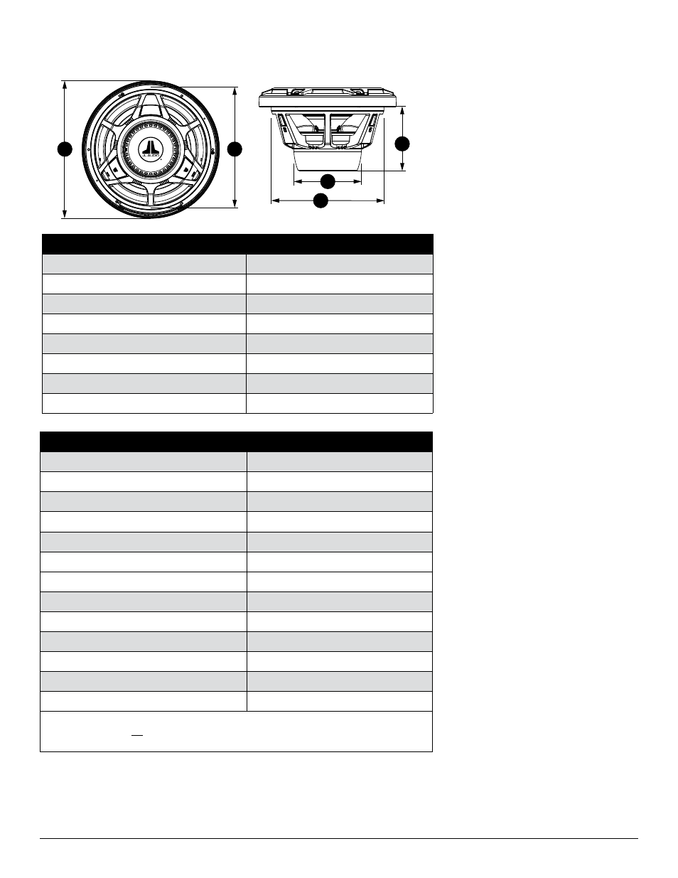
PHYsICal sPeCIFICaTIons
InCluDeD ParTs
• Six #8 x 1 3/8-inch (35 mm) phillips pan-head
stainless-steel screws
• Six #8 stainless-steel washers
subwoofer Physical specifications
Nominal Diameter:
10 in. / 250 mm
Overall Diameter (A):
10.75 in. / 273 mm
Mounting Hole Diameter (B):
8.875 in. / 225 mm
Bolt Hole Circle (C):
9.706 in. / 247 mm
Motor Overmold Outer Diameter (D):
5.29 in. / 134 mm
Mounting Depth (E):
5.12 in. / 130 mm
Net Weight:
6.5 lbs. / 2.94 Kg
Driver Displacement:
0.04 ft
3
/ 1.13 litres
subwoofer Parameters
mX10IB3
Free Air Resonance (Fs):
41.84 Hz
Electrical “Q” (Qes):
0.806
Mechanical “Q” (Qms):
11.751
Total Speaker “Q” (Qts):
0.754
Equivalent Compliance (Vas):
1.29 ft
3
/ 36.53 litres
One-way, Linear Excursion (Xmax)*:
0.42 in. / 10.7 mm
Efficiency (1W/1m)**:
87.23 dB SPL
Effective Piston Area (Sd):
50.68 in² / 0.0327 m²
DC Resistance (Re):
3.957 ohm
Nominal Impedance:
4 ohm
Infinite Baffle Use:
Yes
Enclosure Use:
Yes (Sealed Only)
Power Handling (continuous):
175W
* Xmax specifications are derived via one-way voice coil overhang method with no correction factors applied.
** efficiency (1w/1m) is not an accurate indicator of a subwoofer’s output capability and should not be used
as a comparison to other subwoofers to determine which one is “louder” !