Figure title1 - figure 7 - unit dimensions - front, Tabletitle - table 9: unit dimensions front, Tabletitle - table 10: unit minimum clearances – Johnson Controls AFFINITY 340968-XIM-A-0108 User Manual
Page 11: Unit dimensions - front, Unit dimensions front, 10 unit minimum clearances, Gure 7, Figure 7 - unit dimensions - front, Table 9: unit dimensions front, Table 10: unit minimum clearances
340968-XIM-A-0108
Johnson Controls Unitary Products
11
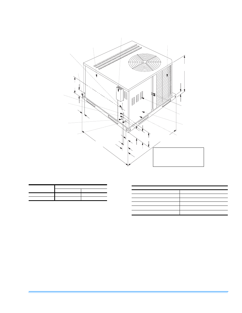
FIGURE 7 - UNIT DIMENSIONS - FRONT
3 - 3 / 4
2 - 1 / 2
4 7 - 1 / 4
1 - 1 / 2
2 - 5 / 8
3 - 1 / 3
5 - 3 / 8
1 1
1 2 - 3 / 4
4 9 - 1 / 8
A
2 - 3 / 8
V E N T A I R O U T L E T H O O D
B L O W E R S E R V I C E
A C C E S S C O M P A R T M E N T
P A N E L
G A S S U P P L Y 1 - 1 / 4 " D I A .
H O L E ( 1 / 2 " N P T I
C O N N E C T I O N )
U N I T C O N D E N S A T E
C O N N E C T I O N 3 / 4 " N P T I
( T R A P R E C O M M E N D E D )
B
H I G H V O L T A G E
C O N N . 1 - 3 / 8 " D I A .
K N O C K O U T
H I G H V O L T A G E
C O N N . 7 / 8 " D I A .
K N O C K O U T
G A S S U P P L Y 1 - 1 / 4 " D I A .
K N O C K O U T ( 1 / 2 " N P T I
C O N N E C T I O N )
L O W V O L T A G E C O N N .
1 - 3 / 8 " D I A . K N O C K O U T
X 7 / 8 " H O L E
C O N D E N S E R C O I L
R E F R I G E R A N T
C O N N E C T I O N S
C O M B U S T I O N A I R
I N L E T L O U V E R S
F R O N T
G A S / E L E C T R I C C O N T R O L
S E R V I C E A C C E S S
C O M P A R T M E N T P A N E L
( O V E R A L L )
( O V E R A L L )
All dimensions are in inches.
They are subject to change with-
out notice. Certified dimensions
will be provided upon request.
TABLE 9: UNIT DIMENSIONS FRONT
UNIT SIZE
DIMENSION
“A”
“B”
018 thru 042
33-1/2
18-1/4
048 and 060
41-1/2
23-1/8
TABLE 10: UNIT MINIMUM CLEARANCES
1
2
1.
A 1” clearance must be provided between any combustible
material and the supply 7 air ductwork.
2.
The products of combustion must not be allowed to accumulate
within a confined space and recirculate.
CLEARANCES
FRONT
36”
BACK
0”
LEFT SIDE (Filter-Access)
24”
RIGHT SIDE
12”
BELOW UNIT
3
3.
Units may be installed on combustible floors made from wood
or class A, B, or C roof covering material.
0”
ABOVE UNIT
4
4.
Units must be installed outdoors. Overhanging structures or
shrubs should not obstruct condenser air discharge outlet.
36” (For Condenser Air Discharge