2 cm-141 pmcl /-ra and cb-141 pmcl, 3 dip switch sw600 – JAI CB-141MCL User Manual
Page 12
CM-141MCL/PMCL/-RA / CB-141MCL/PMCL/-RA
9
5.2.2 CM-141
PMCL /-RA and CB-141
PMCL/-RA
Important Note for PMCL version
CM-141 PMCL/-RA and CB-141 PMCL/-RA cameras feature “Safe Power” circuit which is
stipulated by the PoCL standard. This circuit is used to verify the presence of camera and
PoCL cable before the frame grabber provides power.
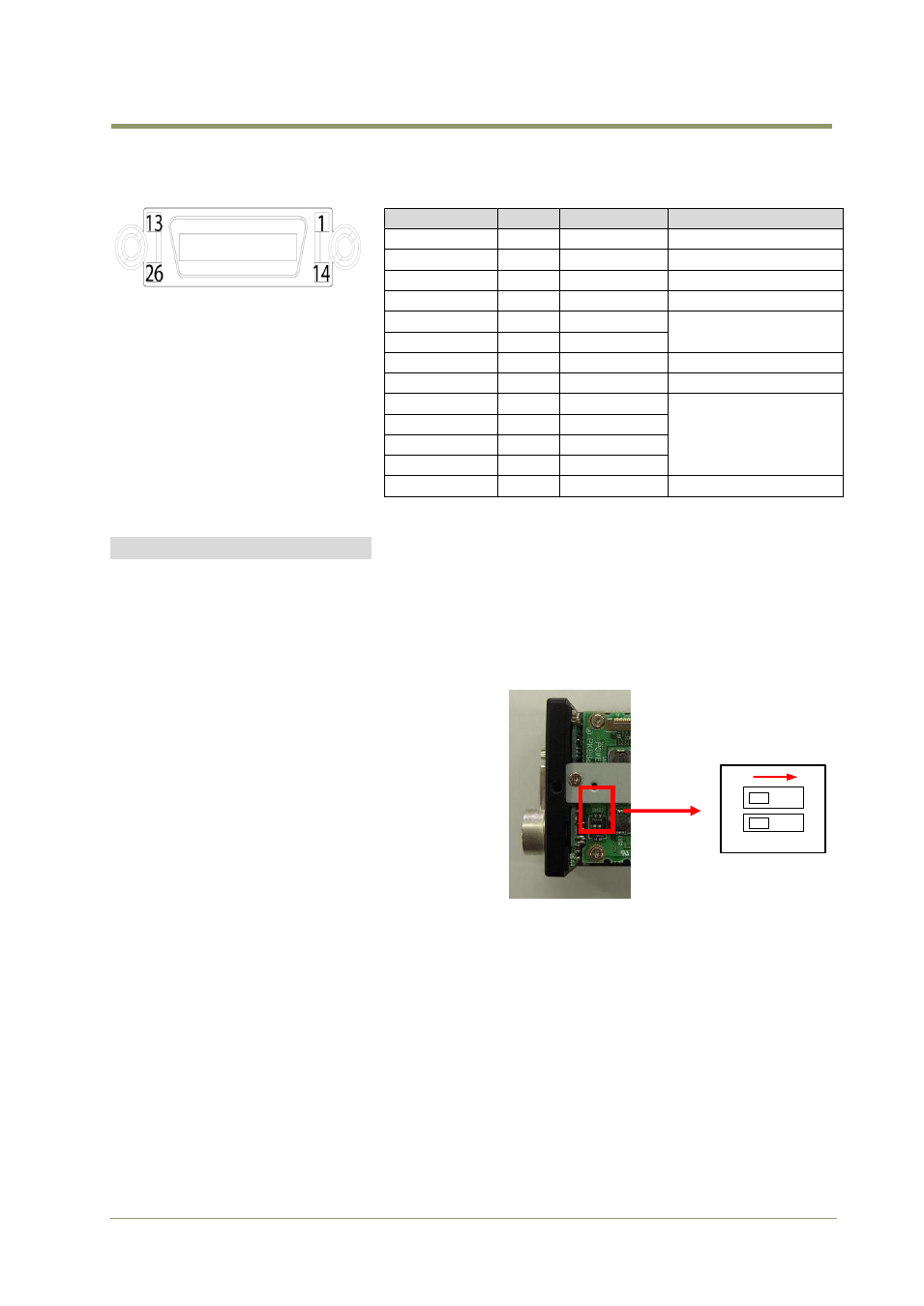
5.3 DIP switch SW600
This is for the selection of TTL or 75 ohm
termination for trigger input.
Factory default setting is TTL.
When DIP switch SW600 is changed, at first
remove the top cover. The factory default is
set two switches to OFF position. In order to
set 75 ohm, two switches should be changed to
ON position.
Fig.6. SW-600 DIP switch
Pin No
I/O
Name
Note
1
I
DC +12V
13
I
GND
For # 26 pin
14
I
GND
For # 1 pin
26
I
DC +12V
7(+),20(-)
I/O
RXD
Serial Com.
8(-),21(+)
O
TXD
10(+),23(-)
I
Reserve
9(-),22(+)
I
Trigger
CC1 Ext. Trigger in
6(-),19(+)
O
TxOUT3
Camera Link out
4(-),17(+)
O
TxOUT2
3(-),16(+)
O
TxOUT1
2(-),15(+)
O
TxOUT0
5(-),18(+)
O
TxClk
Clock for CL
Fig.5. Mini-CL
connector
1
2
O
N
TTL
75 Ω