JAI CB-141MCL User Manual
Page 36
CM-141MCL/PMCL/-RA / CB-141MCL/PMCL/-RA
33
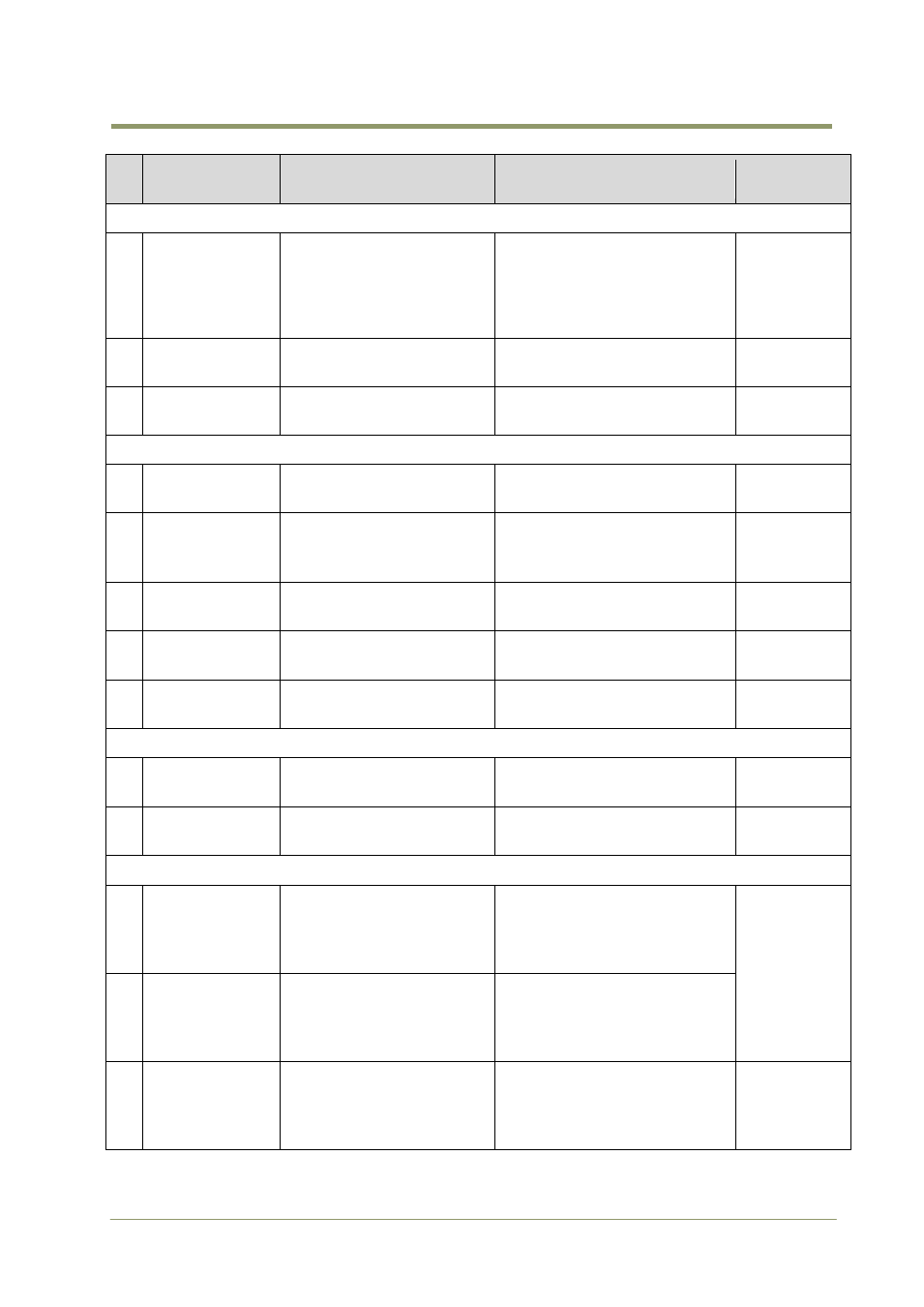
Command
Name
Format
Parameter
Remarks
C - Trigger mode
1
Trigger Mode
TR=[Param.]
TR?
0=Normal (Continuous)
1=EPS(Edge pre select)
2=PWC(Pulse width control)
3=RCT
5=Smear Less EPS
2
Trigger Polarity
TP=[Param.]
TP?
0=Active Low
1=Active High
3
Trigger Input
TI=[Param.]
TI?
0=Camera Link
1=Hirose 12pin
D -Image Format
1
Bit Allocation
BA=[Param.]
BA?
0=8bit, 1=10bit , 2=12bit
2
Scan Format
SC=[Param.]
SC?
0=Full Frame, 1=2/3 Partial
2=1/2 Partial, 3=1/4 Partial
4=1/8 Partial,5= Variable
3
Variable partial
start line
STL=[Param.]
STL?
1 to 1024
4
Variable partial
end line
ETL=[Param.]
ETL?
8 to 1032
5
V-Binning
VB=[Param.]
VB?
0=OFF
1=On
Only CM-
141MCL
E - Gain, Black and signal settings
1
Gain Level
GA=[Param.]
GA?
-84 to 670
2
Black Level
BL=[Param.]
BL?
255 to 767
F - Saving and loading data in EEPROM
1
Load Setttings
(from Camera
EEPROM)
LD=[Param.]
0=Factory area
1=User 1 area
2=User 2 area
3=User 3 area
Latest used
DATA AREA
becomes
default at
next power
up.
2
Save Settings
(to Camera
EEPROM)
SA=[Param.]
1=User 1 area
2=User 2 area
3=User 3 area
Note : 0 is not allowed
3
EEPROM
Current Area No
Request.
EA?
0=Factory area
1=User 1 area
2=User 2 area
3=User 3 area
The camera
return the
latest used
DATA AREA.
NOTE: Do not try to use commands not shown in this list.