Jøtul gz 550 dv ii acadia, Pr oduc t name – Jotul Gas Inserts and Fireplaces User Manual
Page 25
25
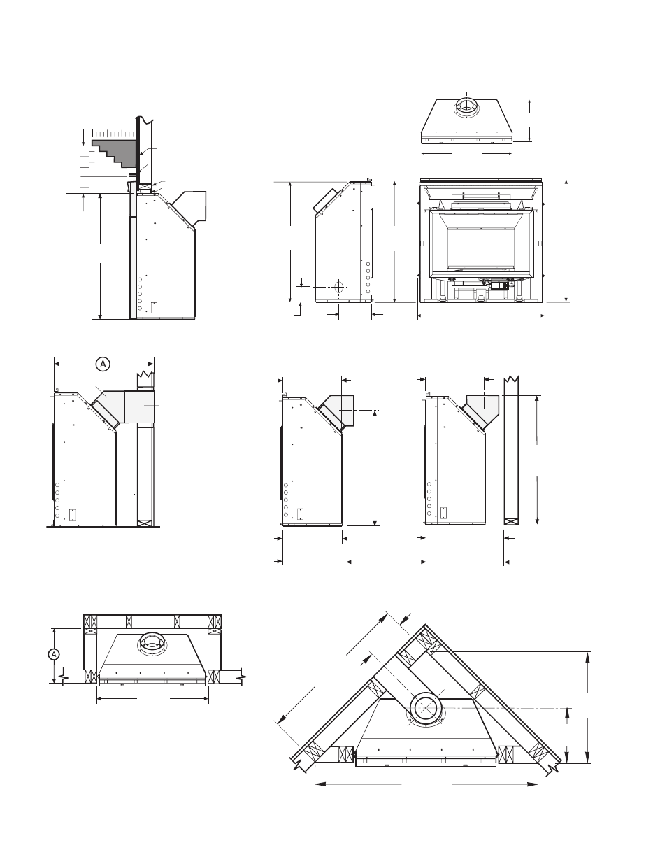
Jøtul GZ 550 DV II Acadia
12” 8” 4”
13 1/2”
10 1/2”
7 1/2”
4 1/2”
9”
12”
Top of
cabinet
35”
Ca
st
ir
on
su
rr
ou
nd
p
an
el
s
Header
Standoff
Upper trim
2 1/2” max. depth
Drywall
Mantel
area
36 1/4”
35 3/4”
8”
4”
35”
900 mm
38”
5/8 Vent Adaptor
6” Vent
Section
38”
Rear Exit
16 1/4”
32 3/4”
16 1/4”
19 1/4”
Top Exit
16 1/4”
38 3/4”
21 1/2”
20”
4/6 Vent
5/8 Vent
9"
41"
56 1/2”
16”
28 1/2”
Clearances
Dimensional views
Rear Exit
16 1/4”
32 3/4”
16 1/4”
19 1/4”
Top Exit
16 1/4”
38 3/4”
21 1/2”
20”
4/6 Vent
5/8 Vent
Vent Adapter Center Lines
Minimum Horizontal Vent Length
Corner Dimensions
Parallel Framing plan
Horizontal vent: Minimum vent accommodates the length
of Vent Adaptor and one 6” vent section through wall
construction.
Vent adaptor: 5/8 - A= 31 3/4
”Vertical Vent: Minimum depth includes 1” clearance
between Vent Adaptor and combustible wall construction.
Vent Adaptor:
5/8
4/6
A=
21 1/2
20”
Horizontal Framing Height = 36 1/2”
16 1/4”
35 3/4”
Security Vent:
A=25 1/4” (645 mm). Security Termination has no slip
adjustability. Simpson DuraVent and Amerivent:
A=25 3/4” (660 mm)
Pr
oduc
t name
Jøtul GI
550
DV Stee
l
A*
Minimum Opening Width
36”
B
Minimum Opening Height
24”
C
Minimum Fireplace Depth
17”
D*
Minimum Back Wall Width
23”
E
Minimum Back Wall Height
23”
Jøtul GI
550
DV
*Subtract 1” if leg leveler brackets are not used
* 16” with plinth
** Add 2” for GI 550 DV cast iron surround with plinth
94449_gas_brochure.indd 25
9/5/07 9:59:24 AM