JBL M9500 User Manual
Page 4
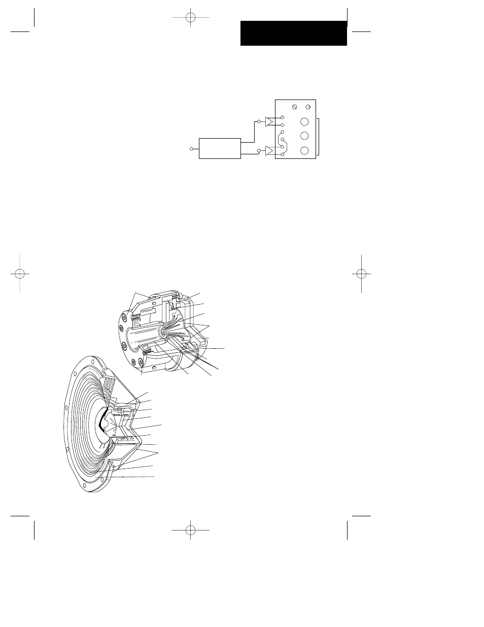
Option D, biamplification. This mode of operation requires a
dedicated electronic dividing network crossing over at 650 Hz.
We recommend the JBL DX-1 with internal compensation
made for the M9500 system. If this mode is used, make sure
that the screwdriver adjustment on the back of each network
is set in the “biamp” position.
High-frequency trim switches on the
back of the networks provide three set-
tings (zero, plus, and minus) so that the systems can be
trimmed for the acoustical characteristics of the listening
space.
Regardless of the operating mode you choose, we recommend
that only the finest hookup wire be used between the ampli-
fiers and dividing networks. We recommend that the wire size
be no smaller than 3.3 square millimeter cross-section (#12
AWG). The inputs to the networks can accommodate spade
lugs, pins, bare wire, or individual banana connectors.
The internal 9-volt battery that is used to bias the capacitors
will normally last at least 5 years. You may test it by pressing
the gold logo on the front of the network. If the LED on the
front of the network illuminates, the battery is functional and
need not be replaced.
The
Transducers
LF1
LF2
R
B
R
Input
B
To M950
D
HF
HF
LF1
LF2
R
0
B
R
B
R
Input
Biamp
Norm
B
+
–
To M9500
HF out
LF out
Electronic dividing
network
(650 Hz crossover)
,,,
,,,
,,,
,,
,,,
,,,
,,
,
,,
,,
,,
,
,
,,
,,
,
,,
,
,
,
,,
,,
,
,
,
,
,,
,,
,
,
,,
,,
,,,
,,
,,
,,
,,
,
,,,
,,,
,,
,,,
,,
,,,
,
,
,,
,,,
,,,
,,
,,,
,,,,,
,,,,,
,,,
,,,
,,
,,
,,
,,
,,
,,
Silver plated pole piece
Front cover
Diecast aluminum housing
Serpentine phone plug
Aquaplas-dusted
titanium diaphragm
Foam acoustic pad
Top plate
Neodymium magnet
Return circuit
Screen
Throat
Threaded mounting holes
,,
,,
,,
,,
,,,,
,,,,
,,,
,,
,,,,
,,,,
,,,,
,,,,
,,,,
,,,,
,,,,
,,,,
,,,,
,,
,,
,,
,,
,,
,,
,,,
,,,
,,,
,,,,,,
,,,,,,
,,,,,,
,,,,,,
,,,,,,
,,,,,,
,,,,,,
,,,,,,
,,
,,
,,,
,,,
,,,
,,,
Aluminum shorted turn
Copper shorted turn
Cooling vent (1 of 3)
Neodymium magnet
Return circuit
Edgewood aluminum
ribbon voice coil
Centering spider
Diecast frame/
magnet chassis
Fiberglas/Aquaplas
composite cone
Foam compliance
Figure 2. Cutaway view of
JBL 475Nd high-frequency
compression driver. Note
the curved (equalized) paths
from the diaphragm to the
driver's output.
Figure 3. Cutaway view of
JBL 1400Nd low-frequency
transducer. Note both
aluminum and copper
shorting rings.
Version 9/14/95 7/27/98 2:58 PM Page 4