Connector pin assignment, Preset modes – Iiyama HM703UT User Manual
Page 23
ENGLISH
9
Input Signal
* Compliant to VESA DDC.
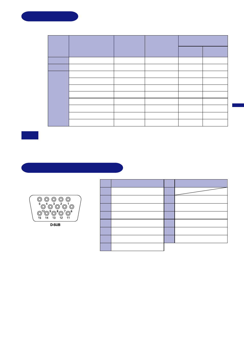
CONNECTOR PIN ASSIGNMENT
D-Sub mini 15pin Connector
Input Signal
3
Red video
Green video
8
Pin
1
2
4
5
6
7
Pin
Blue video
Green video ground
Blue video ground
10
11
12
Data line (SDA) *
13
Ground
Ground
H-Sync
V-Sync
15
14
Red video ground
Clock line (SCL) *
PRESET MODES
The following chart indicates the Factory Preset Modes.
Additional adjustments may be required to the factory-presets, because the signal timings
vary depending on the type of graphics board you use.
NOTE
APPENDIX 19
Ground
Ground
IBM
Positive
Negative
Negative
Negative
Positive
800Ч600
640Ч480
640Ч480
640Ч480
720Ч400
59.9Hz
43.27kHz
Sync Polarity
Vertical
Frequency
Horizontal
Frequency
Resolution
Negative
31.47kHz
Negative
37.50kHz
75.0Hz
Negative
85.0Hz
46.88kHz
75.0Hz
Positive
Positive
Positive
85.1Hz
53.67kHz
800×600
H
V
31.33kHz
70.0Hz
Negative
Positive
Positive
1024Ч768
1024Ч768
68.68kHz
Positive
60.02kHz
75.0Hz
Positive
85.0Hz
VGA
VESA
Positive
1280×1024
79.98kHz
Positive
75.0Hz
Positive
1280×1024
91.15kHz
Positive
85.0Hz